Mods & Tweaks
Table of contents
- Kinematic Bed Mount
- Magnetic Panels with Magnet Inserts
- GCode Buttons
- Funny Pack
- Titanium Backers
- SexBolt Z Endstop
- StealthBurner Beta
- OV5648 and Panzer Observer Camera Mount
- Sturdy Handles
- 6-pin MicroFit Skirt Insert
- Eddie’s LED Bar Clip
- Killw2k’s LCD Display Tweak - Remaining Time
- Future Mods to Consider
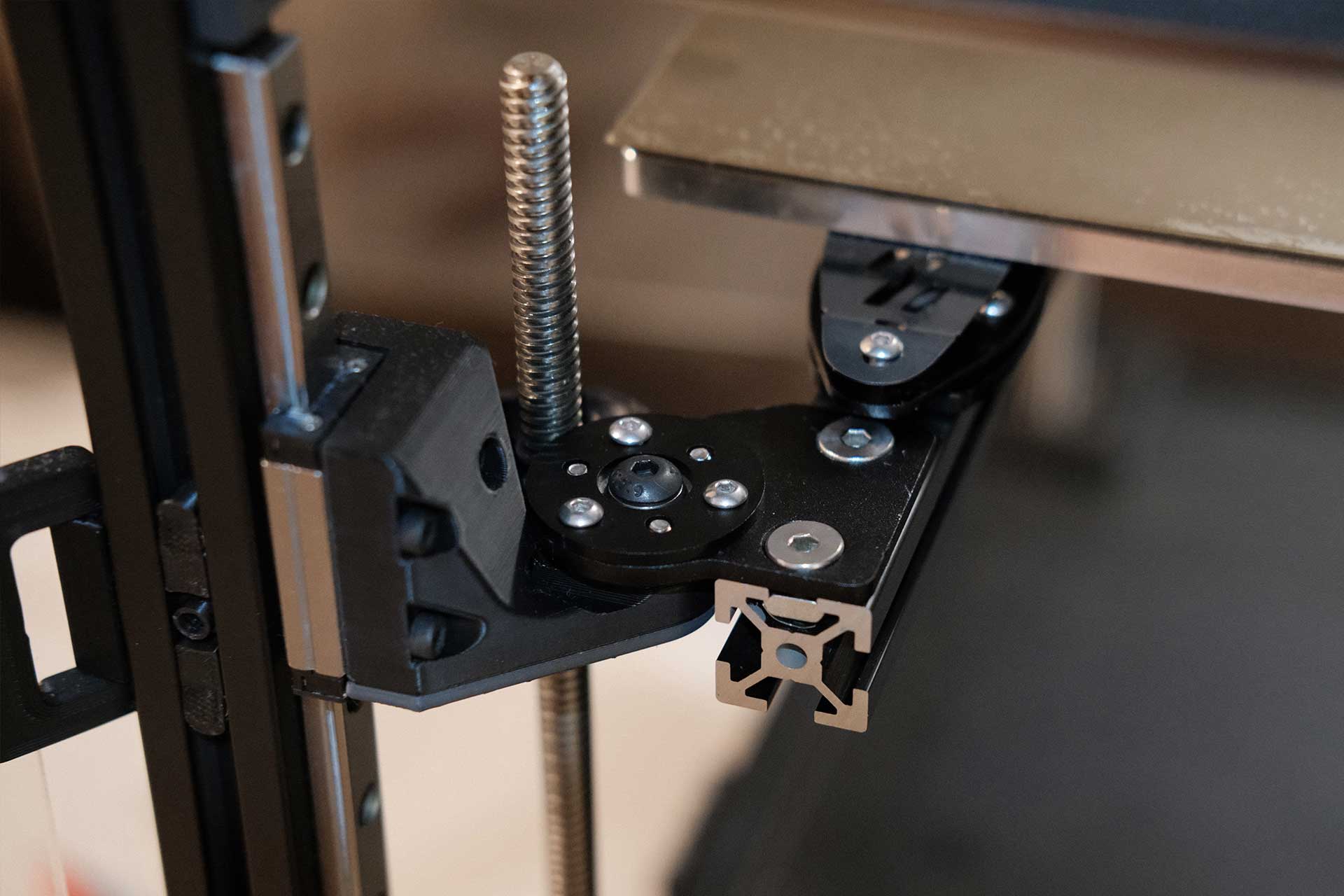
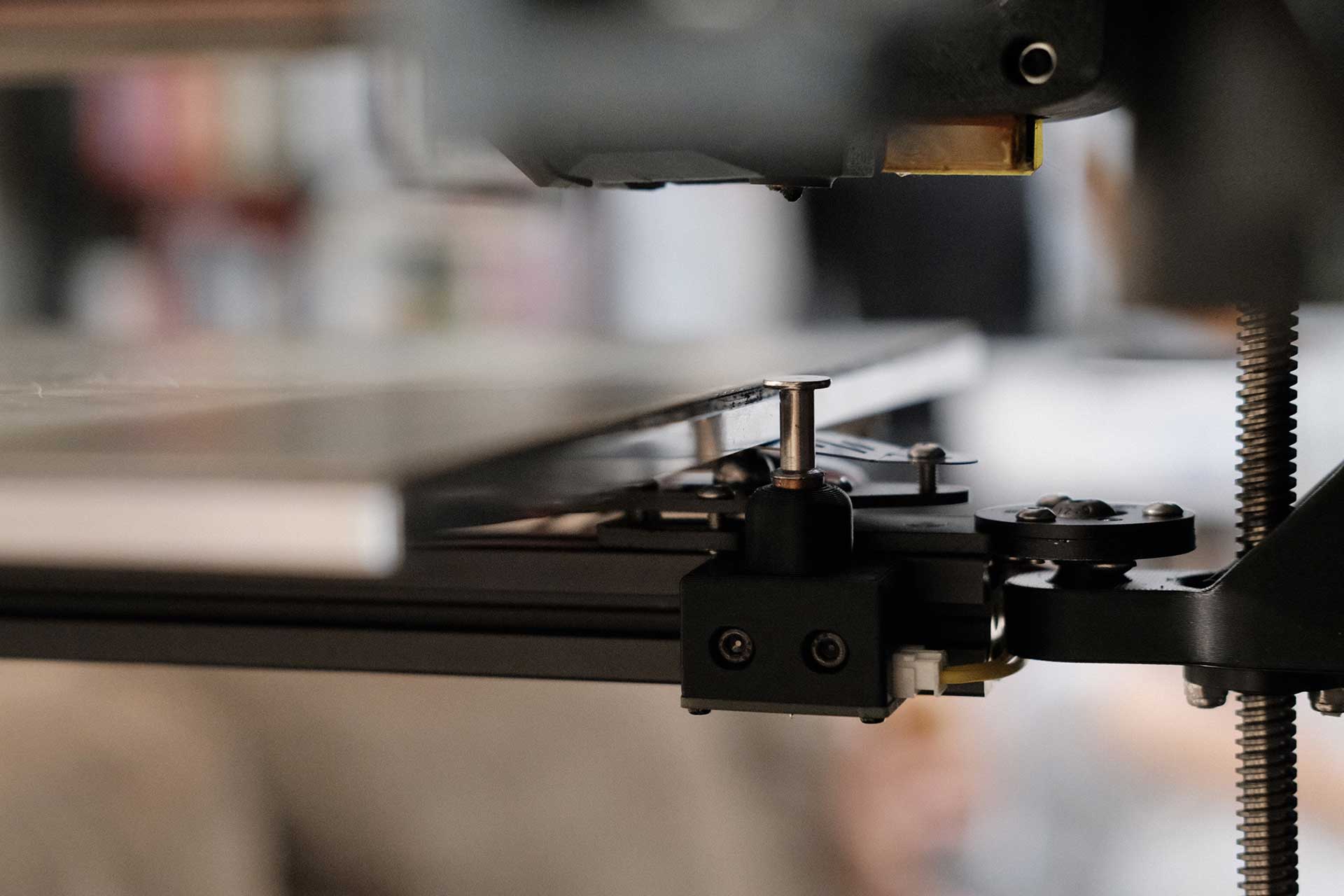
Kinematic Bed Mount
Mandala Rose Works was first to come out with a kinematic bed mount, but their version looks quite bulky and loses about 17mm of Z. I went with the newer laser cut version designed by Whoppingpochard, which only loses 8mm in the Z direction.
Installation was straightforward enough. I did not disconnect my bed and installed one corner at a time, but I don’t recommend this method. While doable, it proabably took 3x as long and was a juggling act at some points, so I would suggest just taking the bed out to make it easier.
Additionally, I used a longer 30mm Chicago screw in the Sexbolt housing to make up for the 8mm taller plate position.
 Kinematic Bed Mounts by Whoppingpochard - 1
 Kinematic Bed Mounts by Whoppingpochard - 2
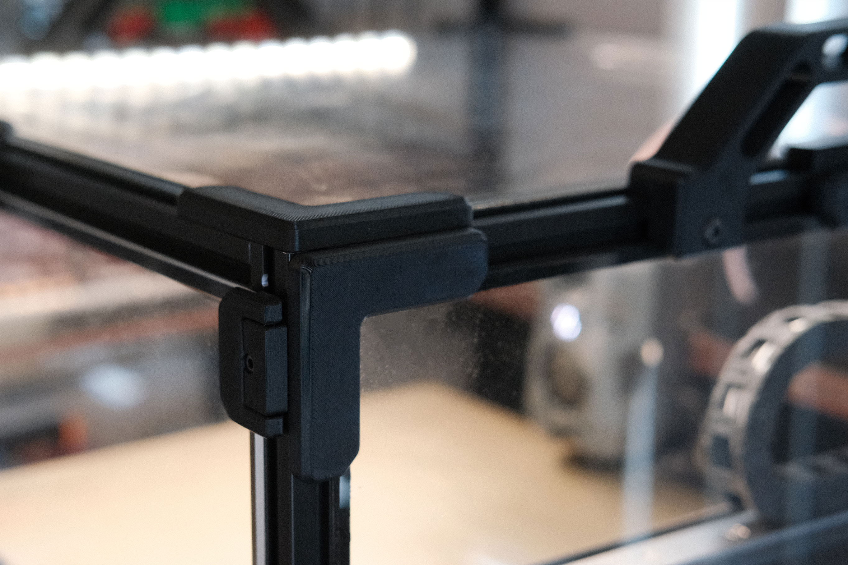
Magnetic Panels with Magnet Inserts
 Magnetic Panels with Magnet Inserts
 Magnetic Panels with Magnet Inserts - Close Up
There are various panel latches and magnetic clips that offer quick panel removal for swapping between enclosed- and open-chamber printing, but I wanted to fix a few of the pain points that I ran into with some of the existing mods.
Does not require a lot of filament. The corner and mid-panel clips were modeled after the stock Trident panel clips and are similarly hollowed, saving filament and print time.
Uses a thin strip of VHB to adhere to the panels. This should provide (1) solid adhesion without the need for drilling or extra fasteners, (2) some amount of squish for the magnets to pull against, and (3) the ability to adjust or remove them in the future.
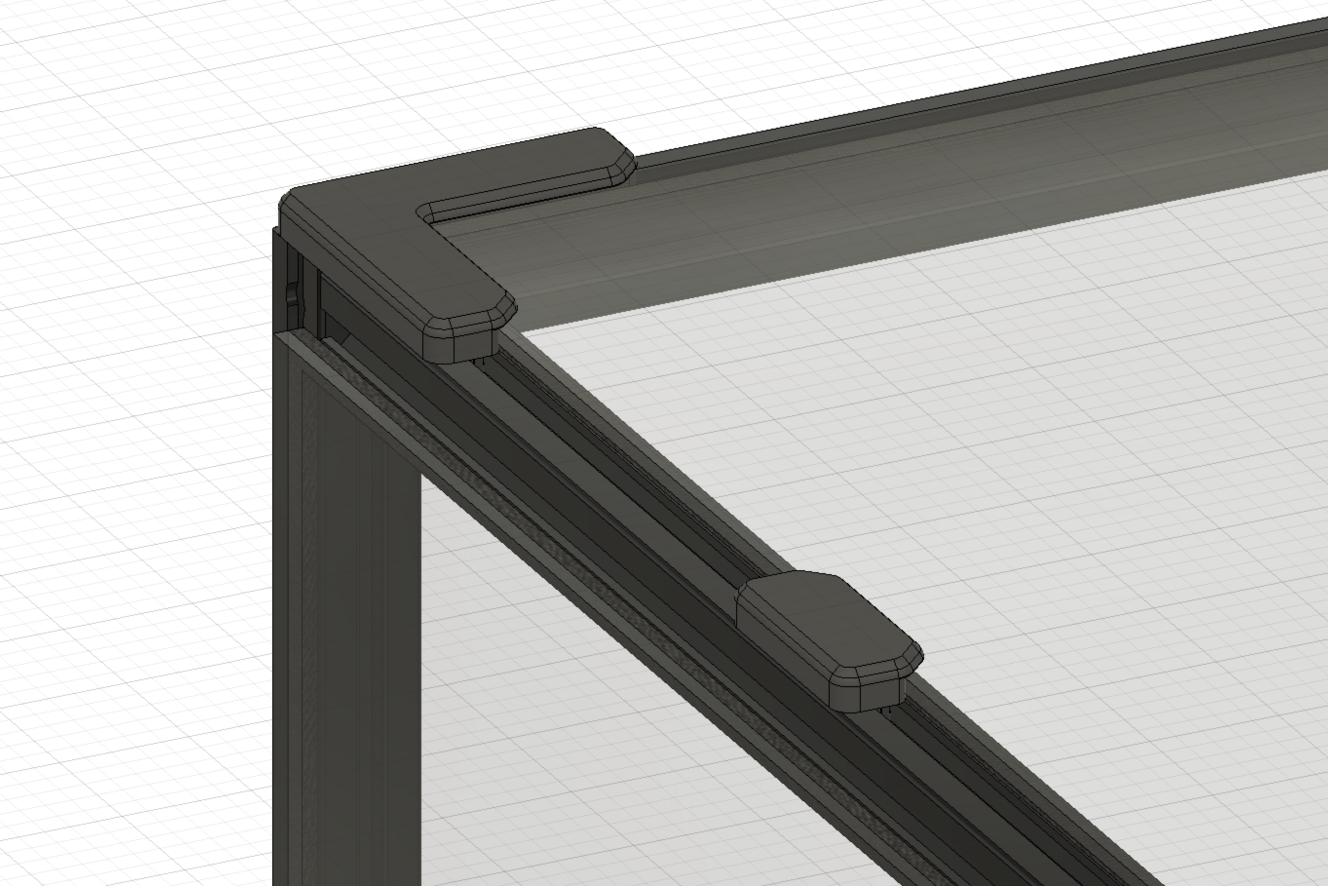
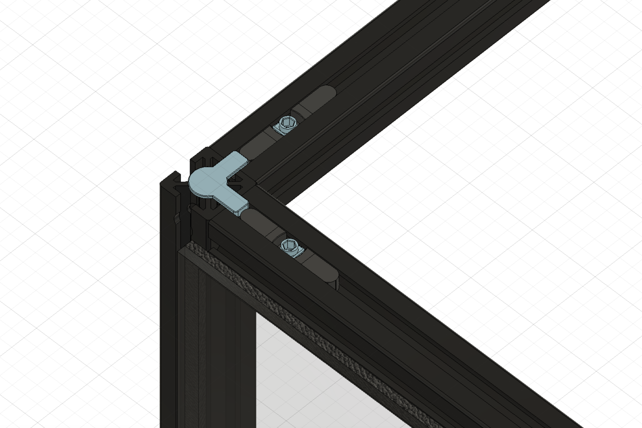
The frame magnet inserts are designed to (1) require only printed parts and no additional fasteners aside from the 6x3 magnets, (2) sit inside the frame slot flush against the aluminum frame face, (3) be easily adjustable, and (4) retain the magnets without glue and allow removal for correcting polarity or salvaging. Discord@PF VT.520 came up with the idea of using a hammerhead-style rotating nut to tighten and press against the magnet insert, holding it in place.
The panel’s ability to sit right up to the face of the frame allows the panels to pop on and off without any interference.
The only required parts are a small amount of VHB tape and a lot of magnets (48 6x3mm magnets for each panel).
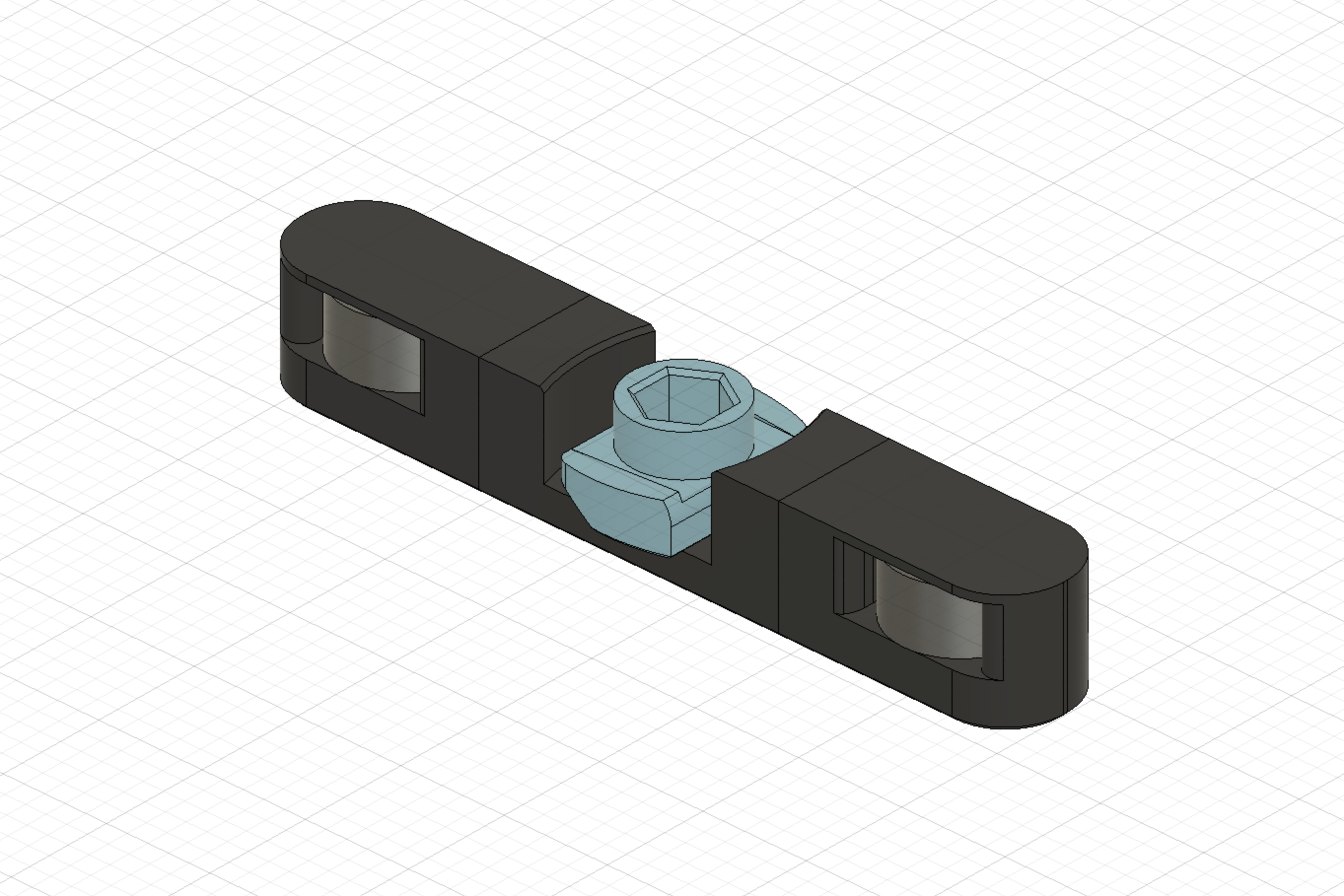 Magnet Inserts
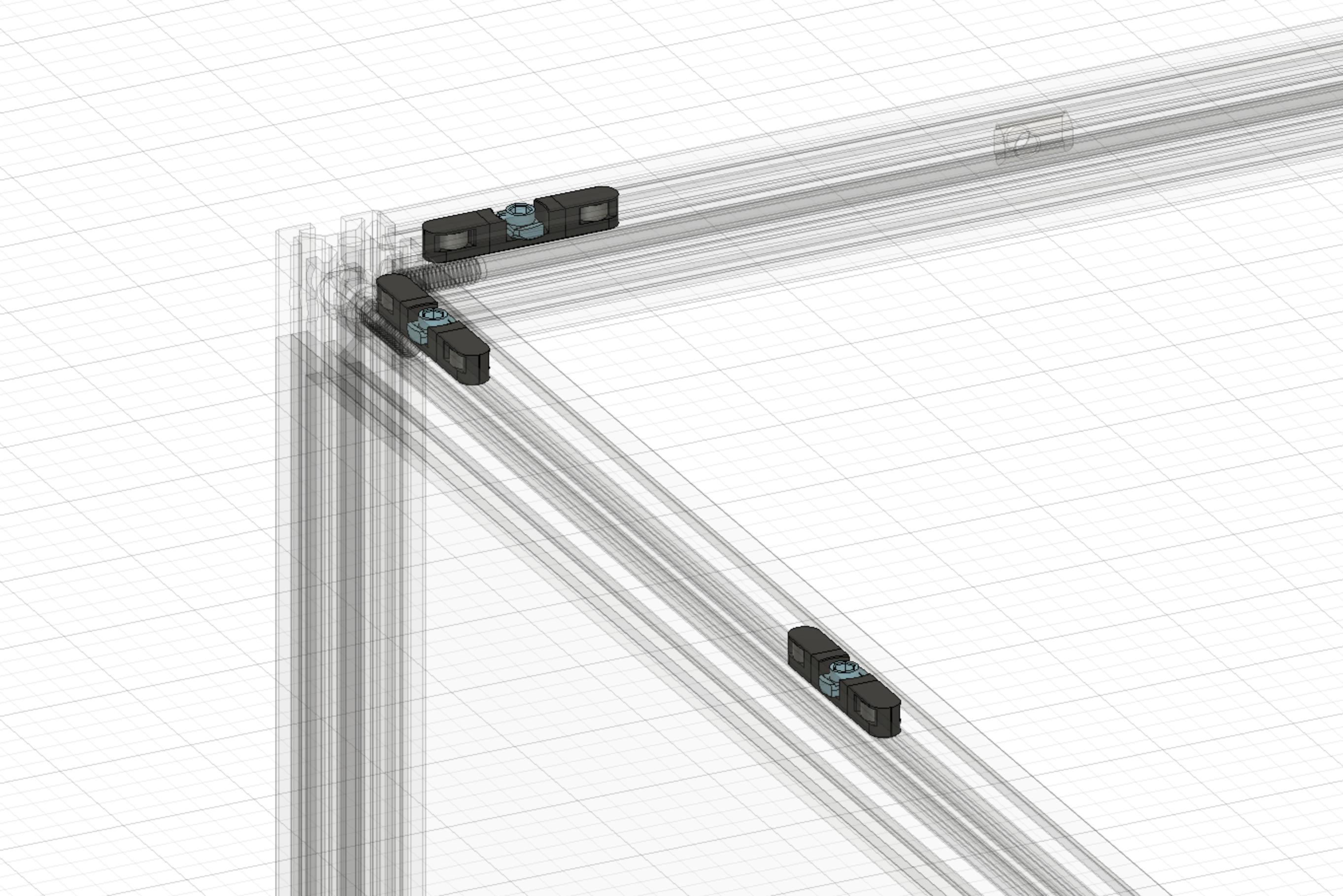 Magnet Inserts in Frame - 1
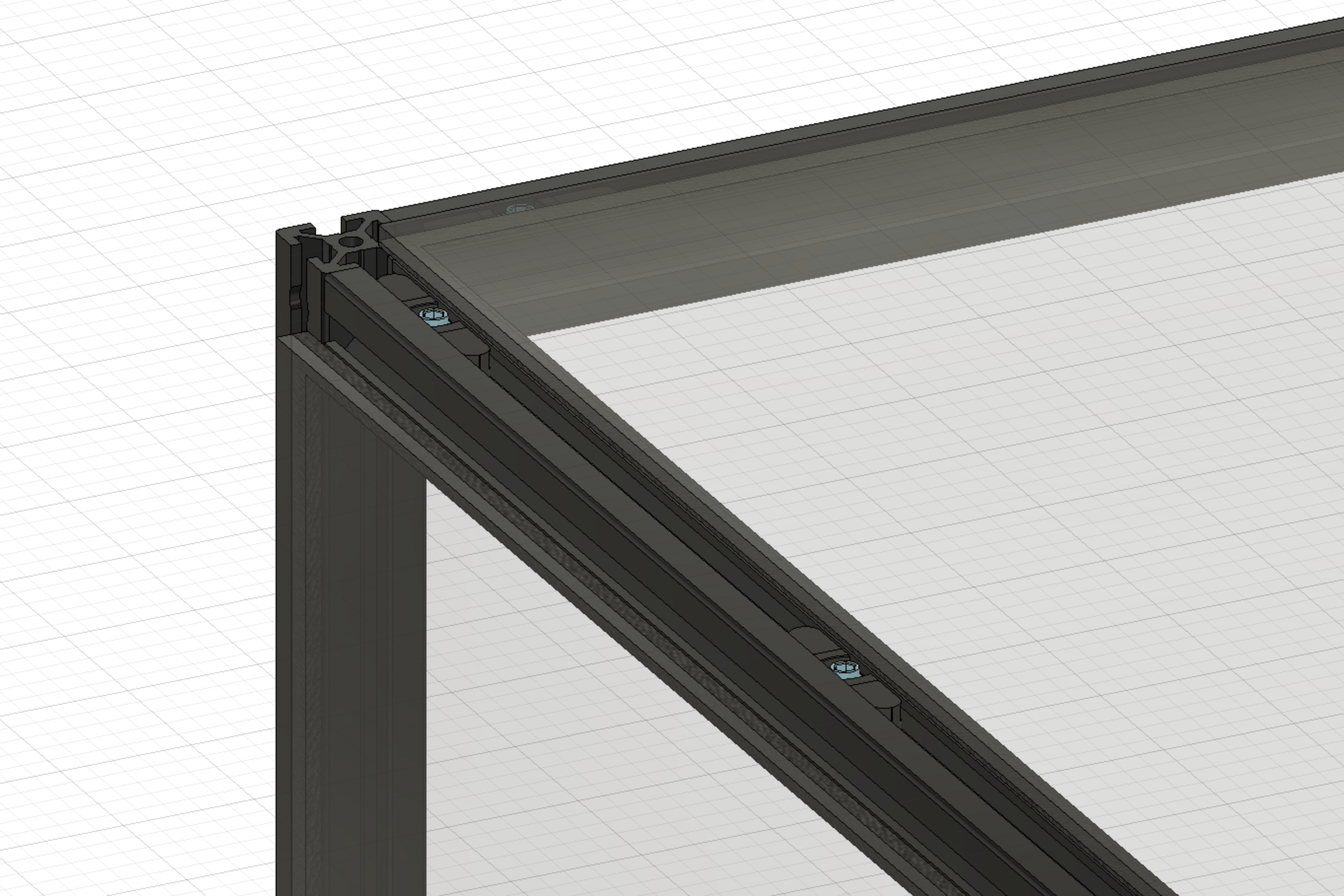 Magnet Inserts in Frame - 2
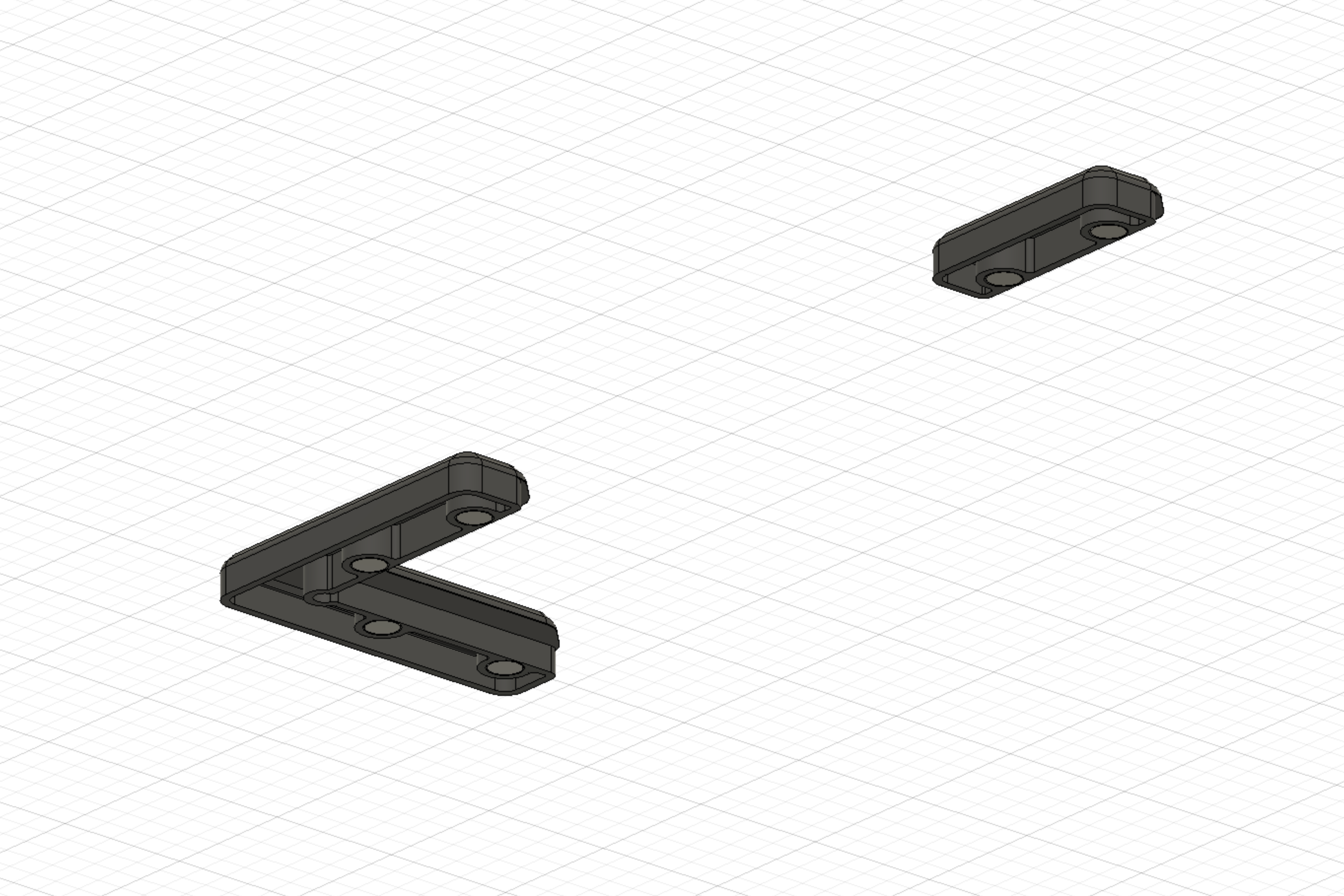 Panel Clips Underside
 Magnetic Panels with Magnet Inserts - Full Install
Update: Designed a jig to make installation of corner clips easy.
 Alignment Jig
Download the STL files for my magnetic panels and magnet inserts
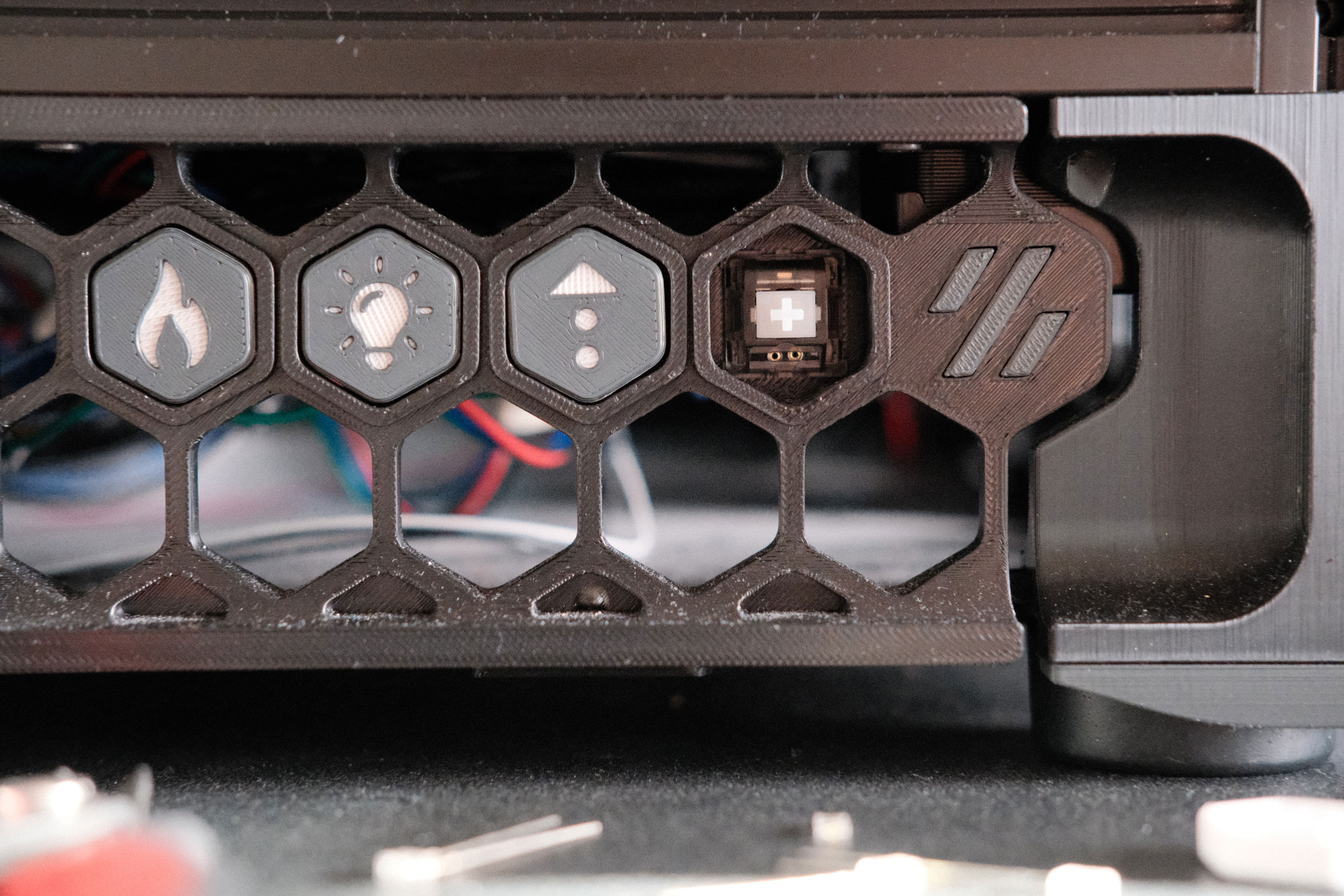
GCode Buttons
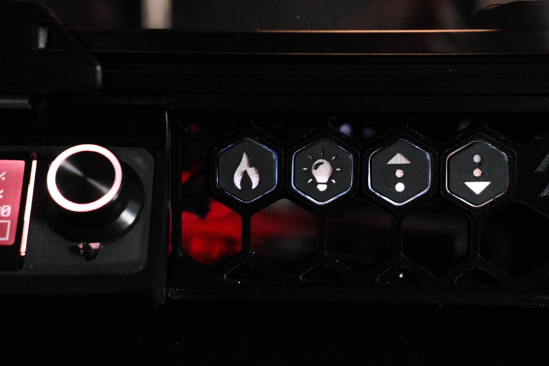
I like Meteyou’s GCode Buttons because they use mechanical keyboard switches for satisfying tactility and are simple to light up with embedded 2x3x4 LEDs.
- Preheat
- Cycles between “cooldown/white dial”, “PLA temp/blue dial”, and “ABS temp/red dial”.
- Max LED
- Chamber lighting is 30% brightness by default. While pressed, this button will temporary increase the brightness to 100%.
- Microstep up
- Increases nozzle-to-bed distance +0.01mm.
- Microstep down
- Decreases nozzle-to-bed distance −0.01mm.
 Skirt buttons
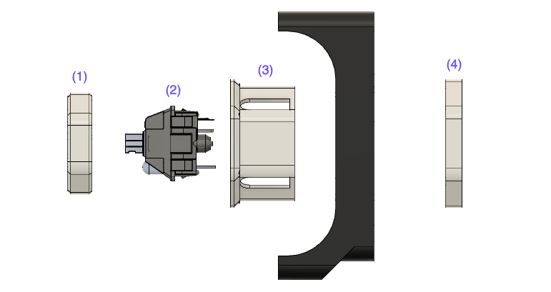
The construction of a button consists of four parts; (1) button, (2) mechanical switch, (3) housing, and (4) lock ring. The mechanical switch is held in the housing, which is inserted through the front of a skirt hex opening, and secured in place from behind with a lock ring.
 Exploded view of Meteyou’s GCode Button
I kept the wiring as simple as possible. One con is that, because the LEDs are installed in the switch housing, they are south facing and the lighting is uneven.
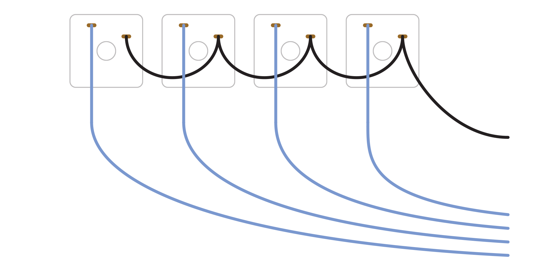
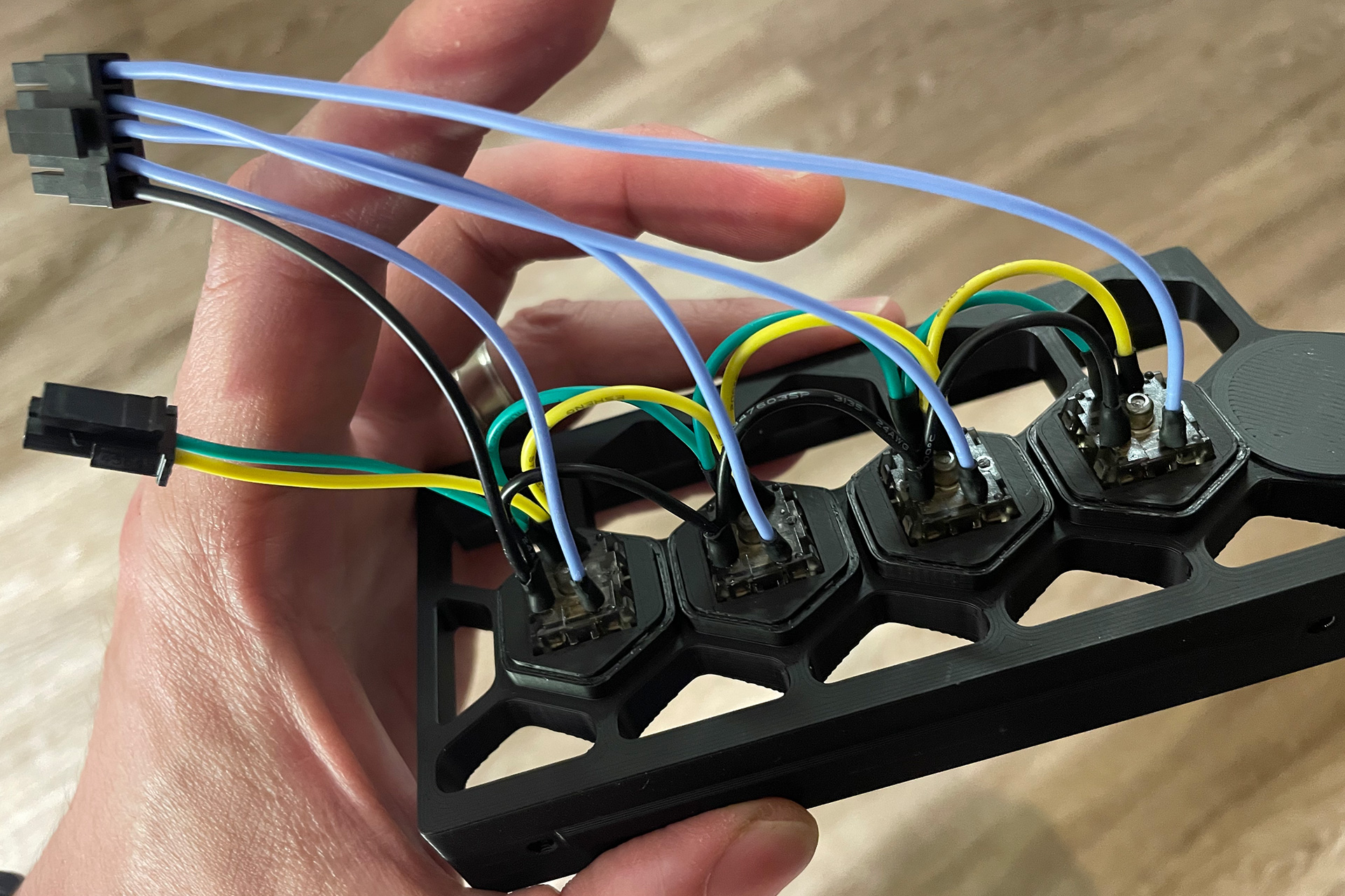
LEDs
Each mechanical switch has an embedded 3V 2x3x4 LED, with the leads poking out the bottom. The positive leads and negative leads are wired inline, and terminate in a MicroFit connector. Since I just want the LEDs on when the printer is powered, I used the Raspberry Pi’s 3V3 power pin (see update below) and ground pin. And, rather than soldering the LED leads directly, I’m using sip sockets as an intermediary. Just like light bulbs and sockets, this makes changing them in the future a cinch.
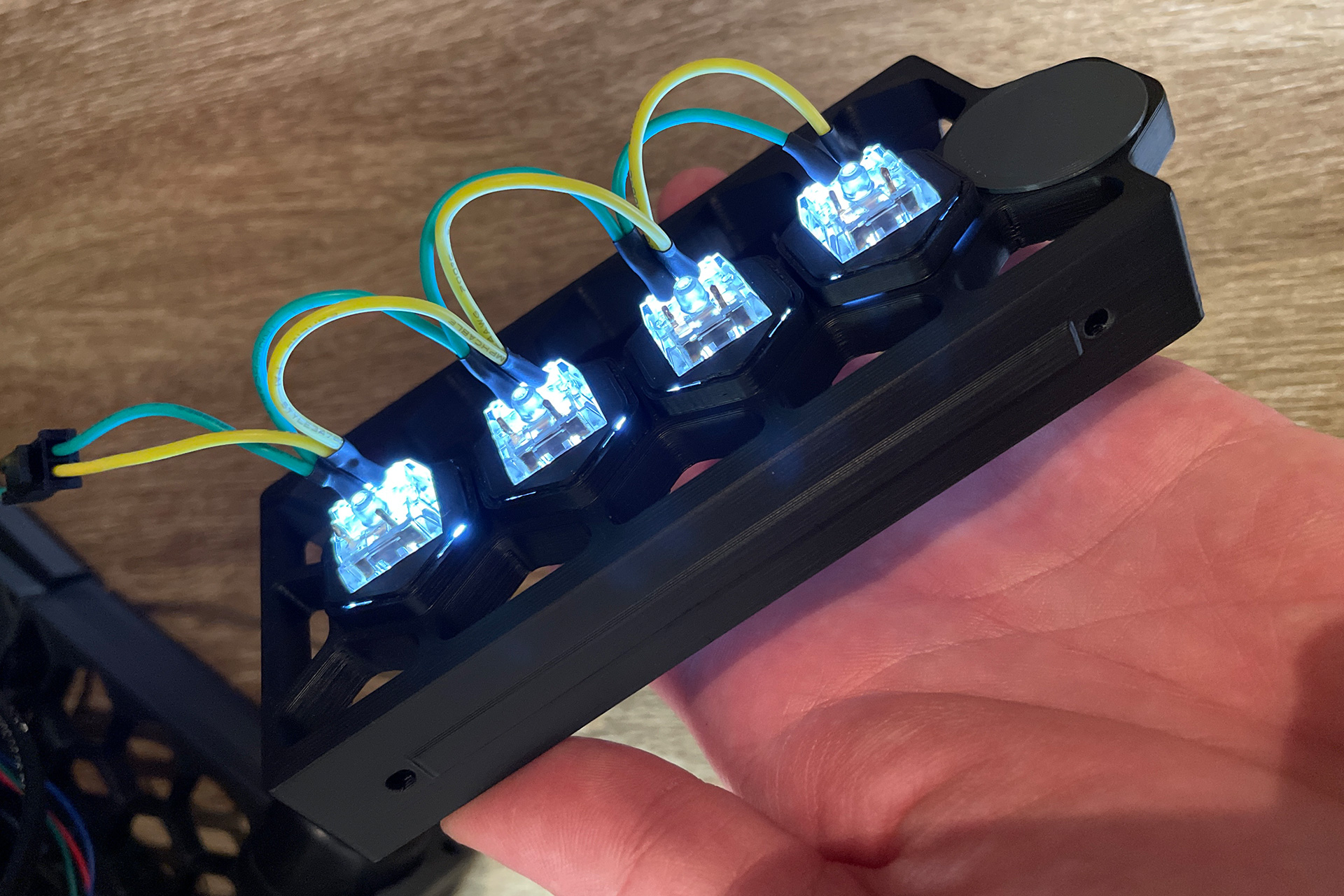 Skirt Button LED Wiring
 Skirt Button Switch and LED Sip Sockets
Update: Having all the LEDs in parallel drew too much current from the Raspberry Pi’s 3v3 pin. I am adding a 30ohm resistor and moving it over to a 5v pin.
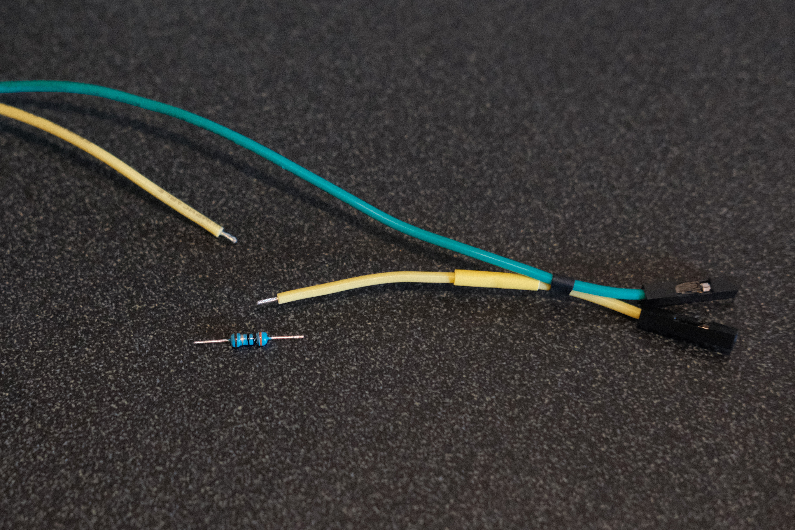 Adding a 30ohm resistor
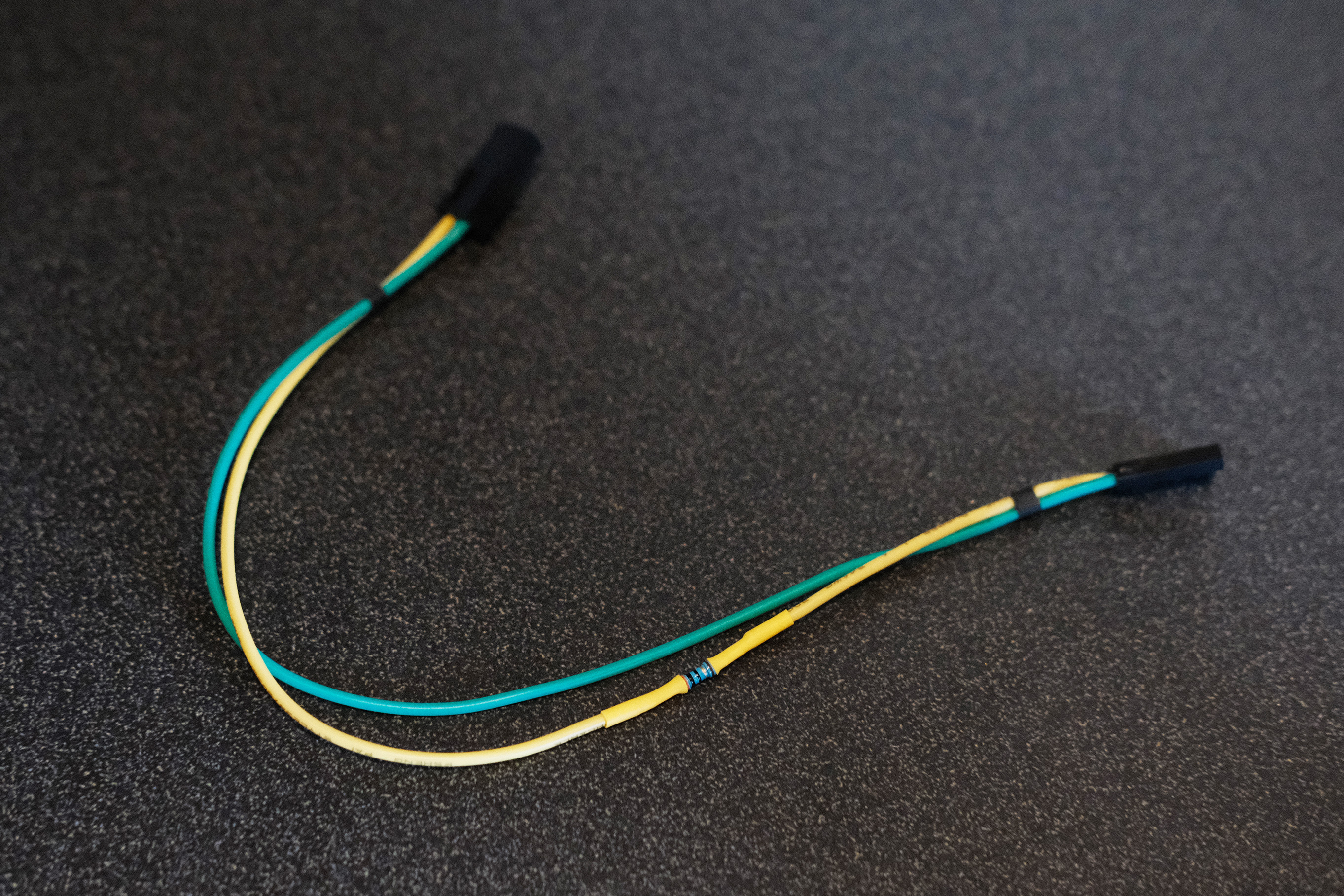 Adding a 30ohm resistor
Mechanical Switches
Each mechanical switch has two pins; ground and signal. The ground pins don’t play a role in the functionality, so all the ground pins can be wired together. The signal pins will each have their own wire so that when pressed, the short can be detected. The 5 wires are then combined in a 5-pin MicroFit. On the other end of each signal wire, they connect to available GPIO ports. I was not able to get this working with the Raspberry Pi’s GPIO pins though, and ended up using pins on my Fysetc Spider v1.1.
 Skirt Button Switch Wiring
 Skirt Button Wiring Complete
The button macros are also easy to set up. You need a pin assignment, “on press” actions, and “on release” actions. Here’s an example for my “microstep up” button:
[gcode_button BUTTON_MICROSTEP_UP]
pin: ^!PC2
press_gcode:
    SET_GCODE_OFFSET Z_ADJUST=0.01
release_gcode:
And for my “max LED” button to see how to handle a button “while pressed”:
[gcode_button BUTTON_CASELIGHT]
pin: ^!PB13
press_gcode:
    SET_PIN PIN=caselight VALUE=1
release_gcode:
    SET_PIN PIN=caselight VALUE=0.3
And, lastly, I created some custom buttons:
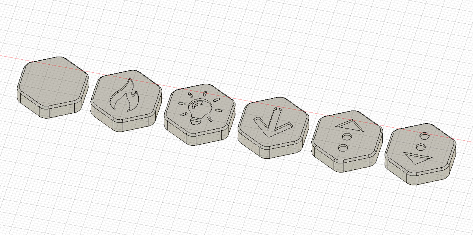 Custom Buttons
To get the LEDs to shine through, I did a filament swap between layers 4 and 5. This results in the fronts of the buttons using my secondary color, KVP Graphite ABS, and the rest of the buttons (including the icon’s fill) using MH Build Series White ABS. Even though I used an opaque plastic rather than a transparent plastic, I find the glow to be acceptable.
Download the STL files for my custom buttons
Funny Pack
The Funny Pack is based on the Fanny Pack which is in turn based on the Nevermore. This exhaust filter uses dual 5015 fans to circulate air through activated carbon pellets (alternative source). Two 1.5” holes need to be cut into the back panel. The printed housing makes for the perfect template to mark where to cut, and going lightly with a 1.5” hole saw with leading drill tip does a pretty good job. The panel will kick and spin during the drilling so clamp it down tight. I ended up needing to print mesh inserts to prevent pellets from falling out of the basket.
Titanium Backers
The aluminum frame undergoes some amount of thermal expansion as the chamber heats up. One way to counteract this is to brace the key extrusions with a secondary type of metal. I sourced titanium backers from 3DMakerParts and the add-ons for M3x6 screws, M3x8 screws, and M3 t-nuts. Stainless steel backers are cheaper, but heavier. The weights for the individual backers are as follows:
- Left extrusion backer - 78.7 gr
- Gantry extrusion backer - 48.0 gr
- Right extrusion backer - 76.6 gr
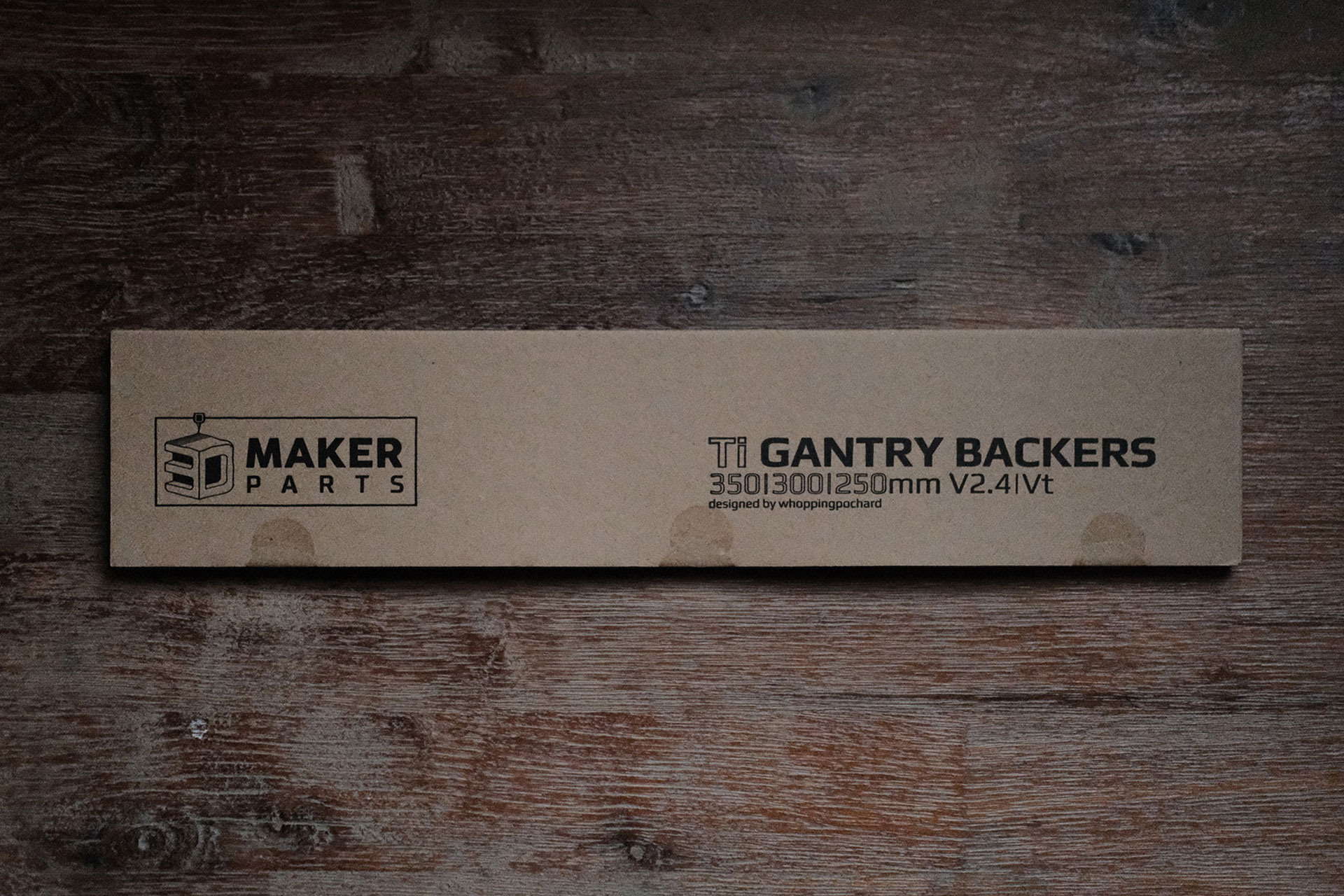 Titanium Backers from 3DMakerParts - Packaging
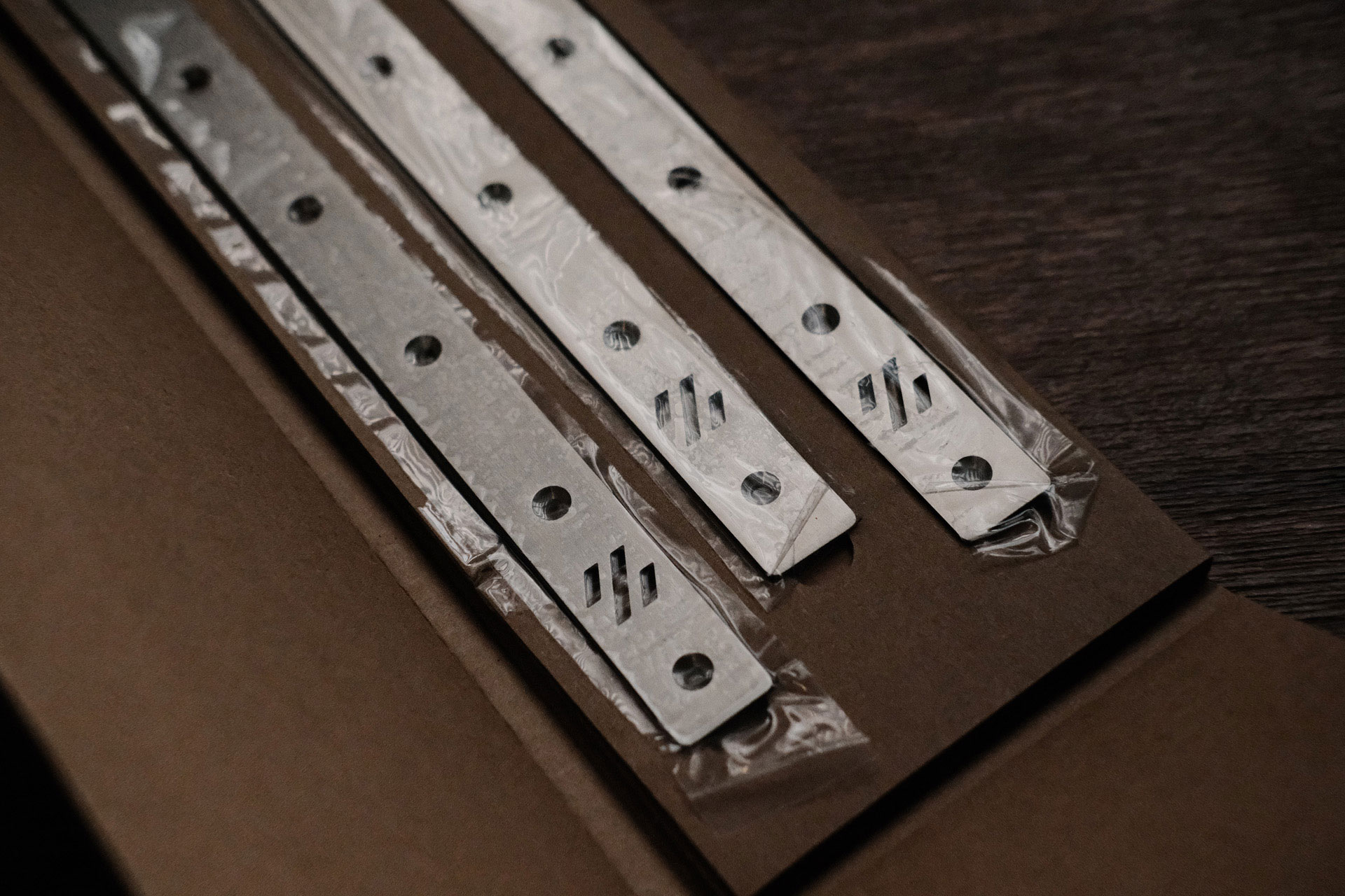 Titanium Backers from 3DMakerParts - Packaging Reveal
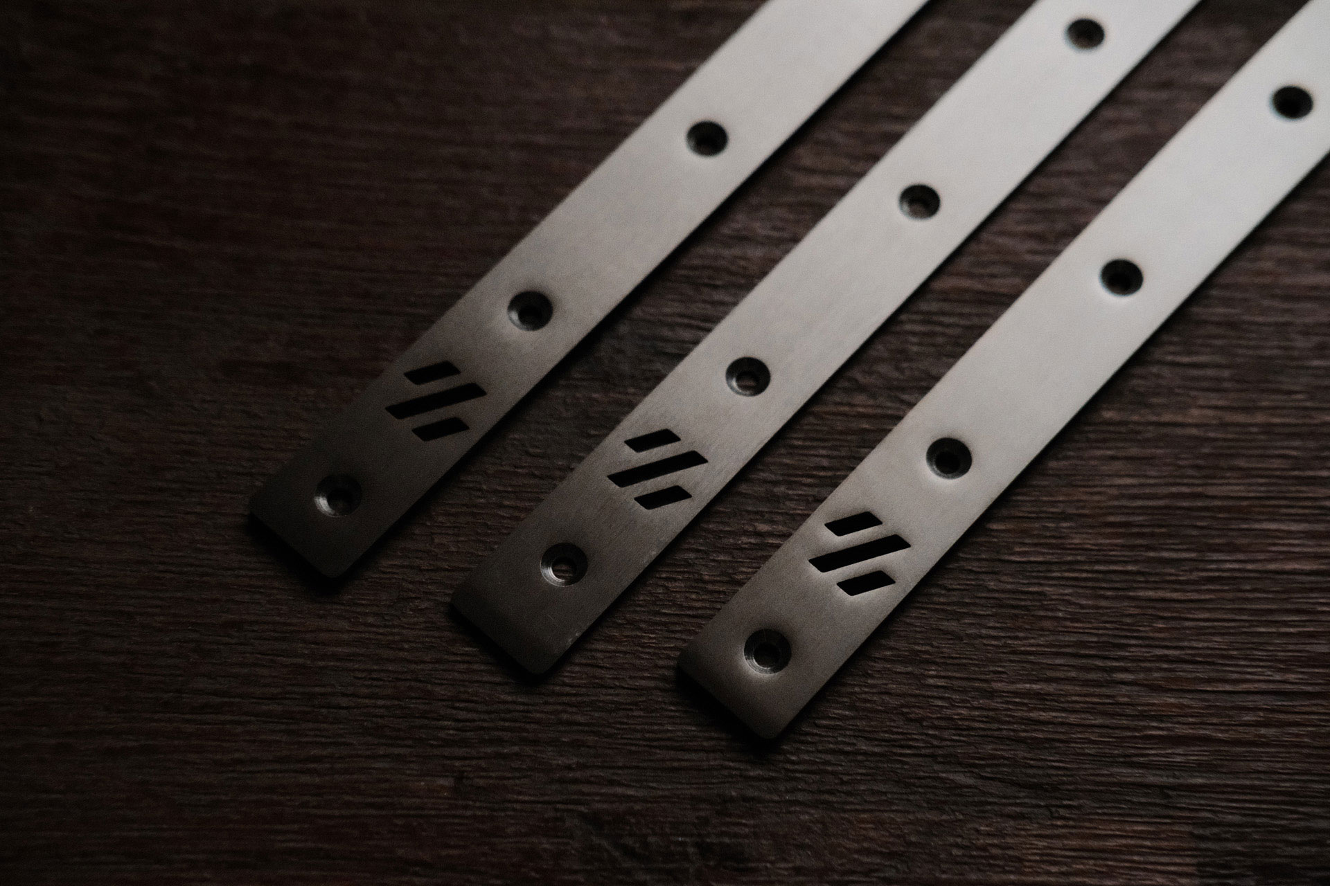 Titanium Backers from 3DMakerParts - Logo
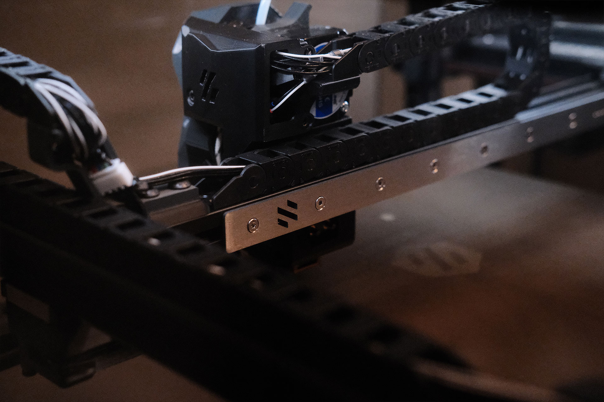
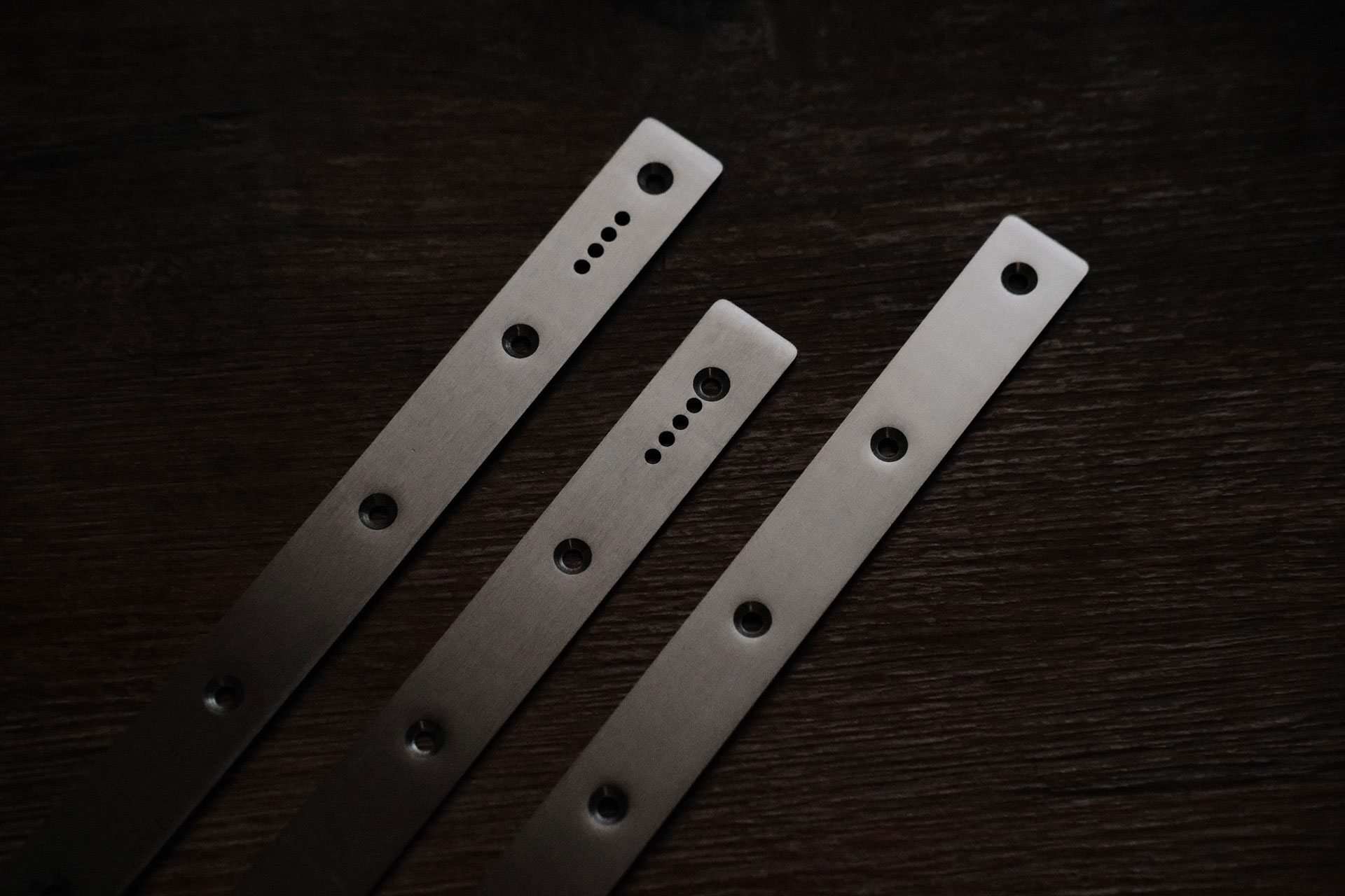 Titanium Backers from 3DMakerParts - Chain Mounts
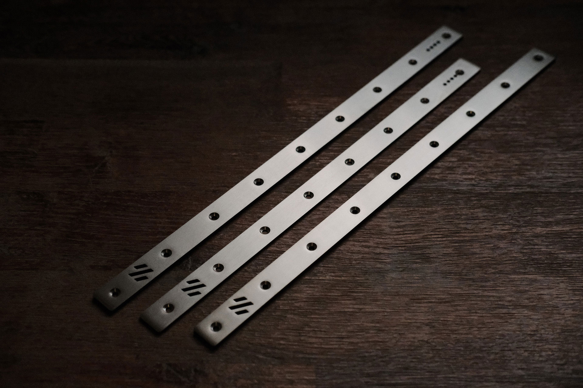 Titanium Backers from 3DMakerParts
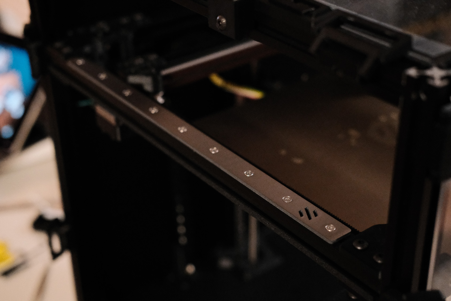 Titanium Backers from 3DMakerParts - Left
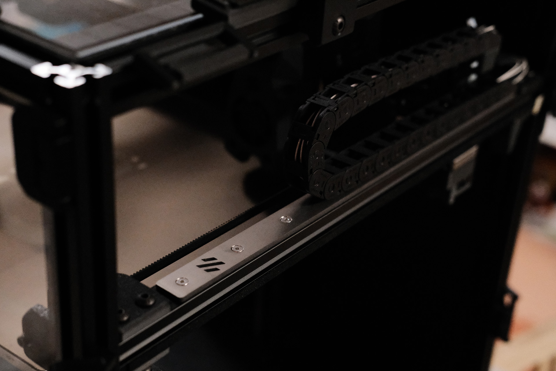
 Titanium Backers from 3DMakerParts - Gantry
 Titanium Backers from 3DMakerParts - Right
To see if there were any measurable improvements, I increased my mesh size to 7x7 and took cold and hot meshes both before and after installation of the backers. Here are the results:
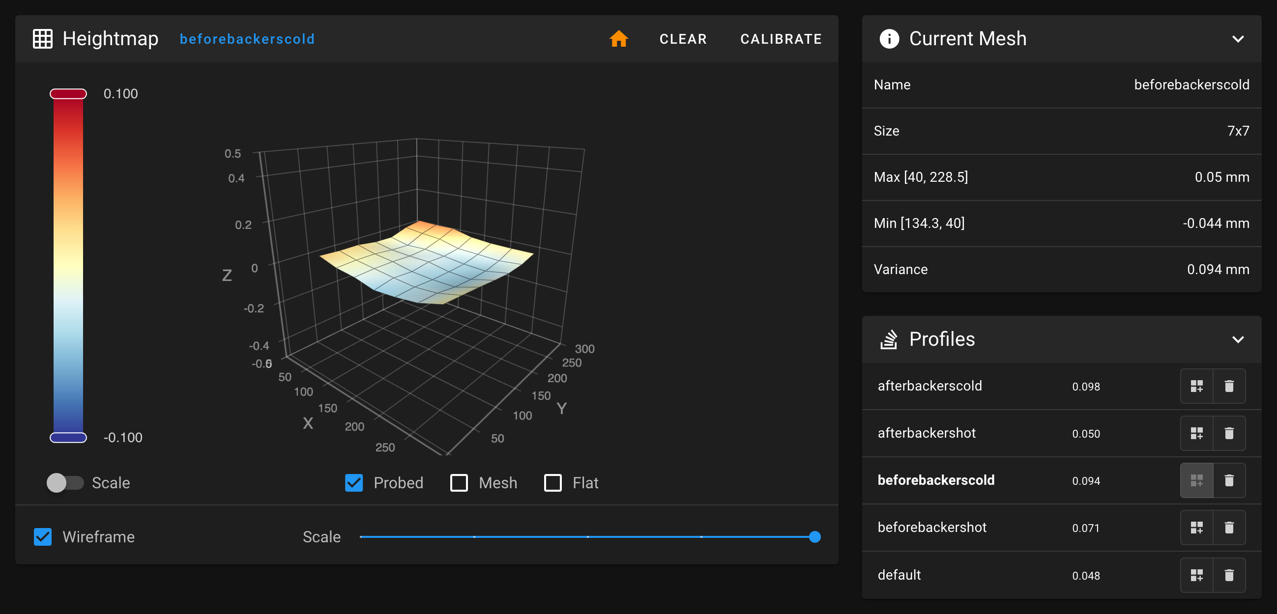 Mesh Before Backers - Cold - 0.094mm total variance
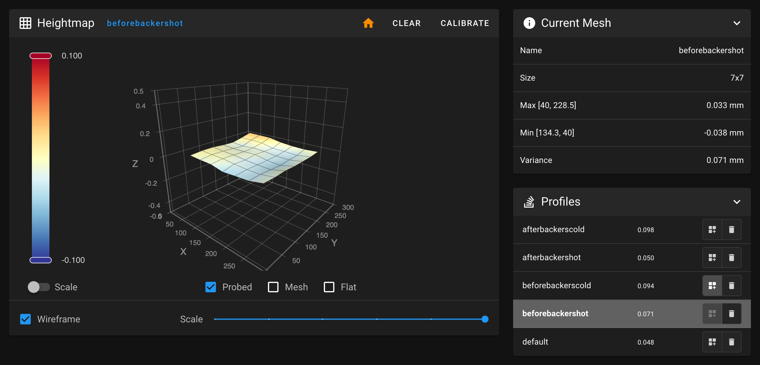 Mesh Before Backers - Hot - 0.071mm total variance
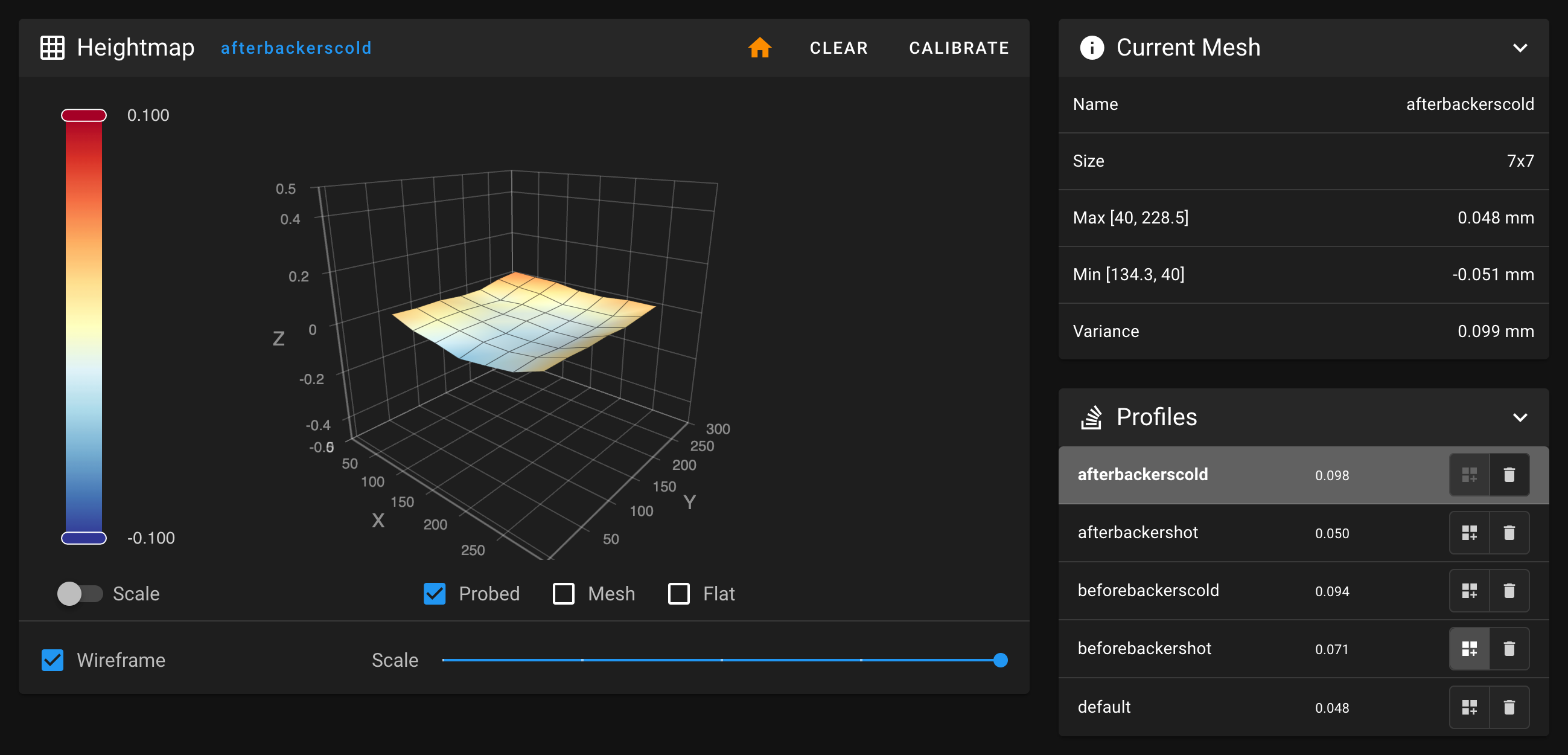 Mesh After Backers - Cold - 0.098mm total variance
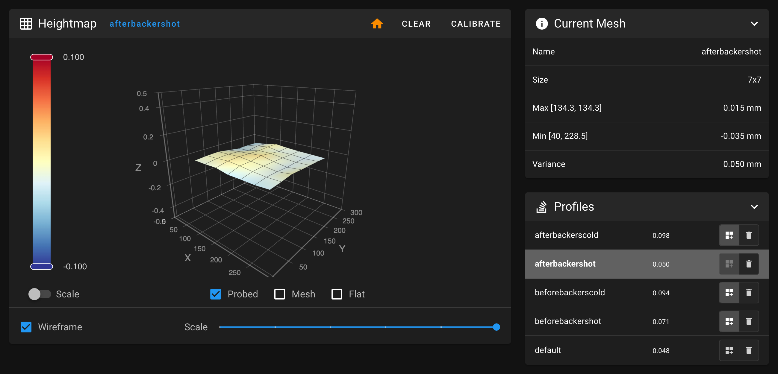 Mesh After Backers - Hot - 0.050mm total variance
Comparing the two hot meshes, the extra side bracing provided by the secondary metal does seem to have helped even out the thermal expansion across the surface area. My first hot mesh after installing the backers showed a total variance of only 0.050mm! After saving the result, I double-checked with another hot mesh and got an even better total variance of just 0.048mm!
Honestly, I would still consider backers to be largely unnecessary. At one point, I was able to adjust my non-backer mesh to a total variance of just .069mm. Having said that, I am still quite impressed by the improvements, and the backers provide a bit more eye candy.
SexBolt Z Endstop
When I switch from printing PLA back to ABS, there’s a bit of leftover PLA filament in the nozzle as it heats up to ABS temperature. I’ve noticed that this overheated PLA ooze has the unfortunate habit of pulling out the Z endstop pin during homing and it’s caused a few nozzle crashes. The SexBolt Z Endstop mod (purchased here) functions exactly the same way as the stock Z endstop, but rather than a smooth shaft, it uses a binding screw with heads on both ends to keep it from falling out.
Fully tightening the M4 screw at the bottom of the pin makes the shaft slightly too low relative to the bed. I added a bit of weak loctite and adjusted the M4 screw until the top of the pin was perfectly flush with the top of the spring steel sheet.
StealthBurner Beta
Using StealthBurner beta and ClockWork2 beta.
- Wire colors for Clockwork2 NEMA14 motor was not consistent with previous Clockwork1 NEMA17 motor even though both are from StepperOnline. I had to find the proper windings (close-circuit wire pairs) by using a multimeter set to continuity mode and listening for beeping indicating a matched pair.
- Ran into issues with under extrusion until I realized my new Clockwork2 NEMA14 motor was 0.9° rather than 1.8° like my previous Clockwork1 NEMA17 motor. Changing
full_steps_per_rotationfrom200to400fixed the issue.
Update: Finally got around to wiring and installing the Neopixels. They really do add a lot of flair to the toolhead.
- White
- Standby
- Red
- Nozzle preheating to or at ABS temp
- Blue
- Nozzle preheating to or at PLA temp
- Green
- Homing
- Purple
- Z-Tilt
- Yellow
- Calibrating mesh
 Stealthburner with Neopixels
Julianschill’s Klipper LED Effects
Giving this library a shot. The default macros for Stealthburner’s neopixels are thorough, but only offer on/off states. This library has special effects like breathing and fades.
OV5648 and Panzer Observer Camera Mount
For an in-chamber camera, I decided on trying a variant of the OV5648 camera with manual focus and a slightly wider camera angle and mounting it under the rear X extrusion on the opposite side from the Z cable chain. For the mount itself, I am using the Panzer Observer for the slim profile, rotation, and minimal hardware. The default cover’s square camera cutout was too small for my slightly wider lens, so I modified the CAD file to a circle instead, and removed the other unnecessary cutout.
Update: The mount is too long to attach to the extrusion where I originally planned. For now, I have it VHB taped to the rear panel in that same area. The perspective is pretty good; I can see the homing and tilt routines, but it’s missing part of the bed.
Update 2: I’ve designed a new mount, body, and cover that will fit within the space, even on a 250mm build. The spacer will push the mount past the existing gantry printed parts. The mount has a center slot to accommodate one or two screws that will go through both the mount and spacer to drop-in M3 nuts inside the aluminum extrusion, and the mount has a recess to clear the M5 button heads on the A motor printed part. The overall length of the body and cover have been shortened as much as possible. This setup is flexible and can slide anywhere along that particular extrusion to fit any Trident build size. On any other extrusion, the mount can be used without the spacer. Cable relief has been removed from the original mount and added to the body of the camera housing to keep everything tidy.
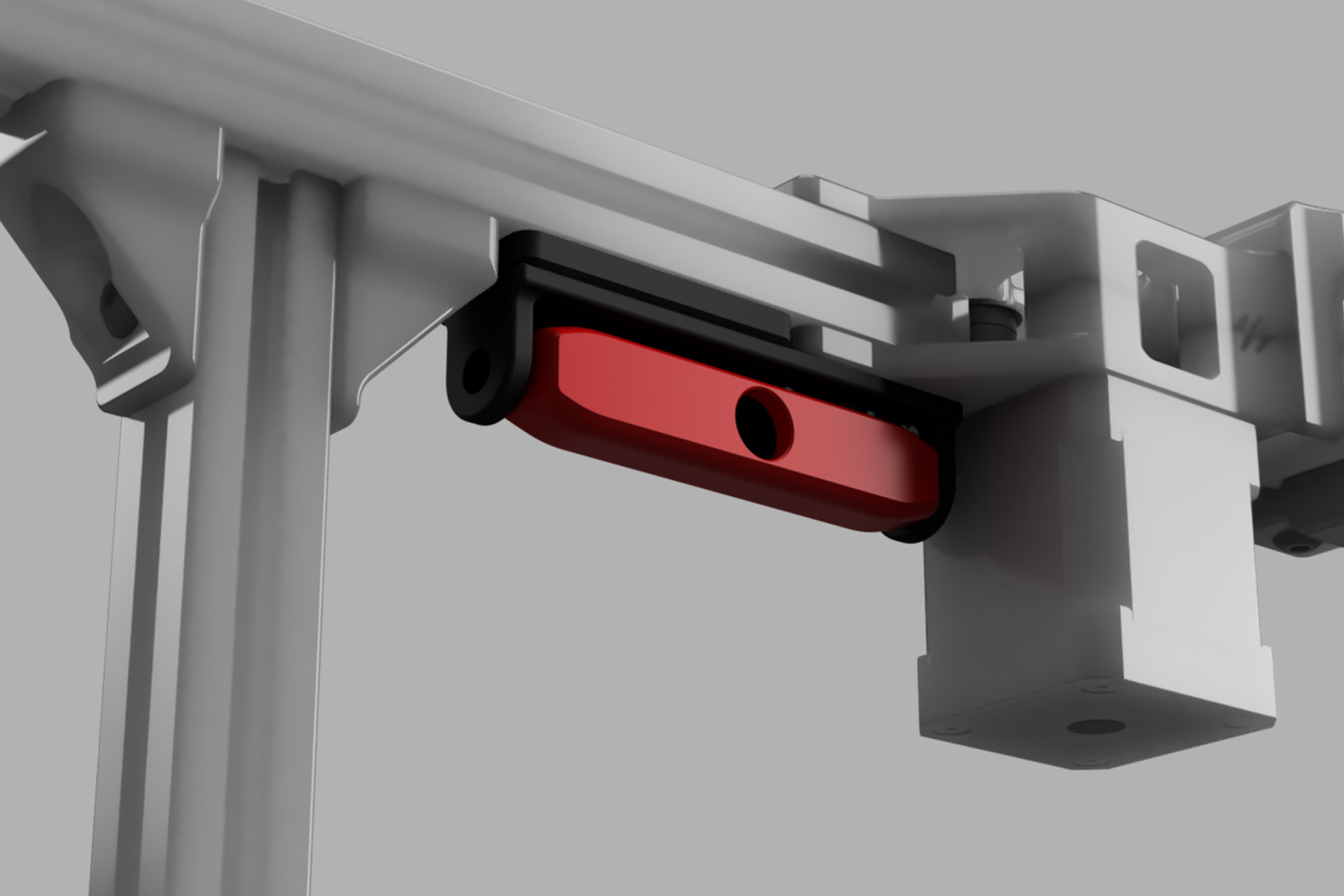 New OV5648 Mount
Update 3: The install was a lot fiddlier than I imagined. Tight quarters meant screws kept getting blocked and were tricky to tighten. And the socket head screws did not have enough clearance with the body to allow for tilt adjustment. Luckily the angle it defaulted to is pretty much as good as it can get from that position.
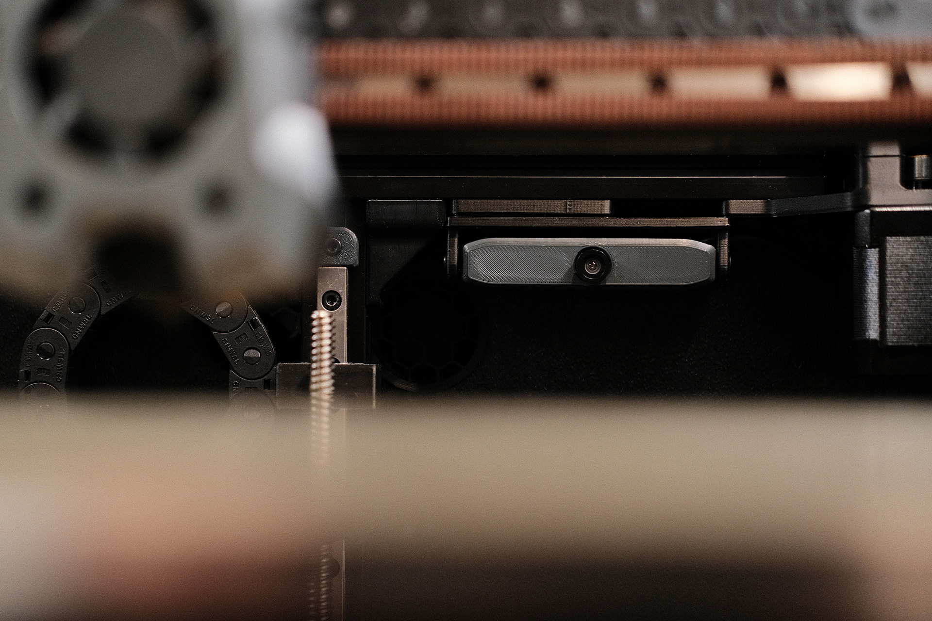 OV5648 + New Mount
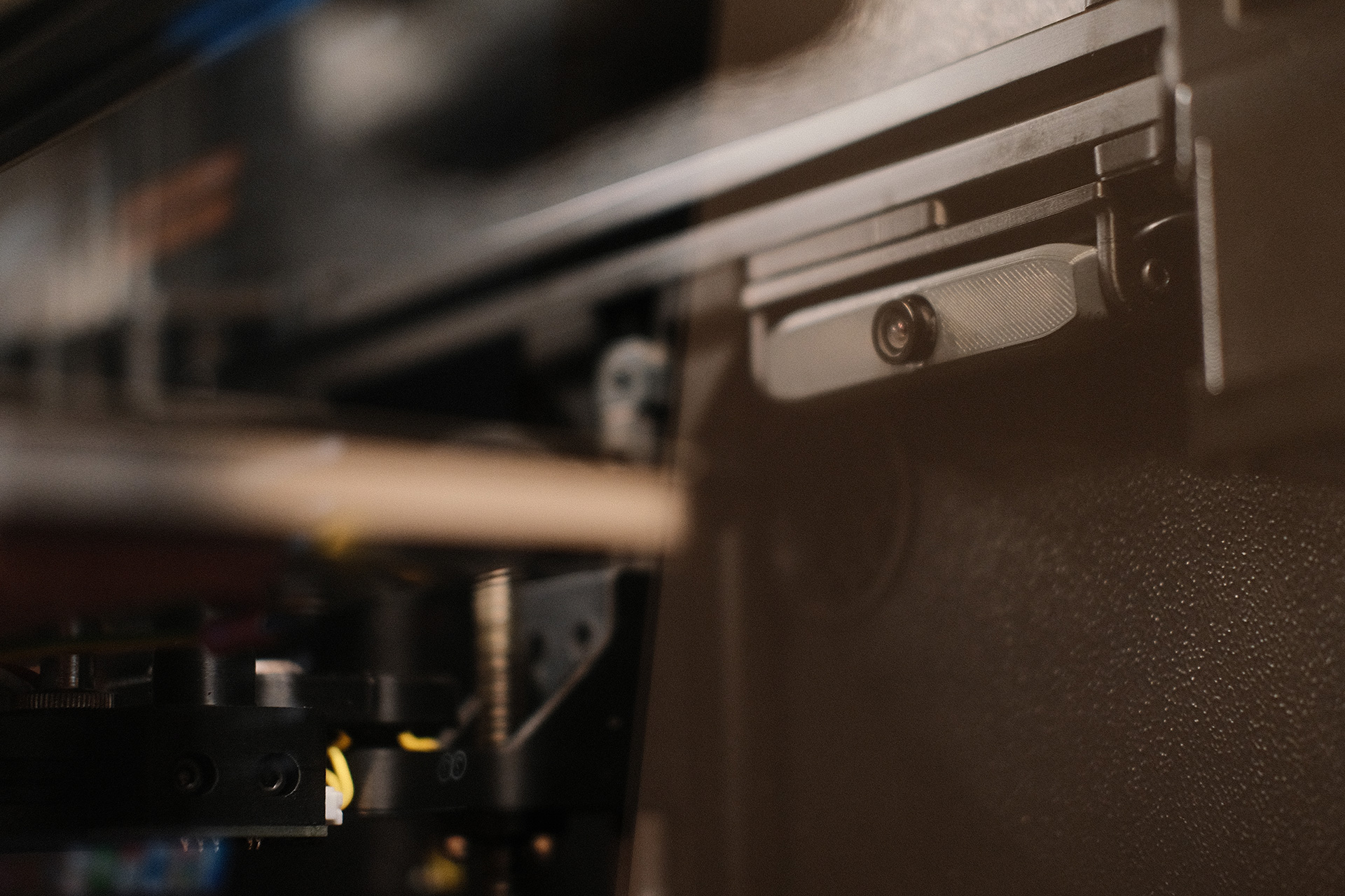 OV5648 + New Mount
Download the STL files for my OV5648 Camera Mount
Sturdy Handles
Sturdy Handles mount well and do not interfere with panel removal, but the extrusions have a tendency to rotate. Need to remember to periodically retighten the frame.
6-pin MicroFit Skirt Insert
Two sources for this mod; 6-pin MicroFit Skirt Insert and the Lock. Provides an interface for the ADXL345 cable to make Input Shaper calibration easier.
Eddie’s LED Bar Clip
Everyone likes Eddie’s LED Bar Clip. Easy to print, clips directly to 2020 extrusions, and have baffles to shield light from eyes. I did not extend the LED mounts fully from front to back, and chose to leave some room. Just in case I need space to mount a camera in the future. Check out Steve Build’s stream to see how to wire them together into one 4-pin dupont connector.
Killw2k’s LCD Display Tweak - Remaining Time
I found Killw2k’s LCD Display Tweak - Remaining Time mod on Reddit. All it does is move the progress bar to the bottom row to make room for displaying remaining time and total time, neither of which are shown by default.
Future Mods to Consider
- Better Filtration System, Discord@PF VT.520
- Pepe Pack - Improved Fanny Pack with heatset inserts rather than VHB tape, better wiring channels, finer mesh on filter basket.