Gryphon & Gryphle0n
Table of contents
Introduction
The Gryphon is an open-source flywheel blaster designed by Flygonial and available on Github. Most up to date CAD files can be found here.
Features
(Pulled from the Github page)
- Uses 130 to 180 sized 20.4mm , brushed DC motors.
- Semi-auto by rack and pinion with 1:3 gear multiplication. The trigger pull is fairly short at 12mm.
- Accepts 33 to 38mm OD flywheels (all 2mm shaft fit, superstock upgrade flywheels).
- Utilizes a horizontal flywheel cage that bolts directly onto the magwell. This is a mounting pattern less prone to misalignment than a Stryfe’s mounting bosses or similar.
- Accepts Worker Talon mags, Katana-geometry mags with a lower release cut-out, and almost all full-length magazines.
- Battery is located in the stock or a side battery tray.
- Full-length feed guide integrated in magwell for maximum feeding reliability.
- Bore-axis is almost as close as possible to top rail of blaster, which is theoretically more intuitive to aim with.
- Will fit on build volume as small as 120 mm3.
In my opinion, the Gryphon platform is solid, easy to print, relatively easy to assemble, and offers a lot of modding and upgrade potential. The Gryphle0n is my slightly modified version where superfluous decorations have been removed, some parts tweaked for better printability, and utilizes heatset inserts anywhere screws go directly into plastic.
 Gryphle0n & Gryphon
 Gryphle0n Front
 Gryphle0n Grip
 Gryphle0n Middle
 Gryphle0n Top
Build Guide
BOM
- 2 x 130/180 motors
- 33-38mm, 2mm shaft-fit flywheels
- 16-18AWG multi-strand hobby wire
- XT60/XT30 connectors (2 female, 1 male)
- Heatshrink
- 21A full-size microswitch
- 2 x 20mm steel pins
- 0.5mm coil thickness, 5mm diameter, 15mm compression spring
- 0.5mm coil thickness, 5mm diameter, 50mm compression spring
- 4 x M2x4 FHCS
- 8 x M3x6 SHCS
- 22 x M3x8 SHCS
- 2 x M3x10 SHCS
- 4 x M3x12 SHCS
- 1 x M3x16 SHCS
- 2 x M3x20 SHCS
- 4 x M3x25 SHCS
- 4 x M3 nuts (Gryphon) or 34 x M3 heatset inserts (Gryphle0n)
Cage
 Mount Motors
Double check the motors’ polarities, make sure the motors are fully seated, and that the shafts appear parallel to each other and perpendicular to the mounting.
- 4 x M2x4 FHCS
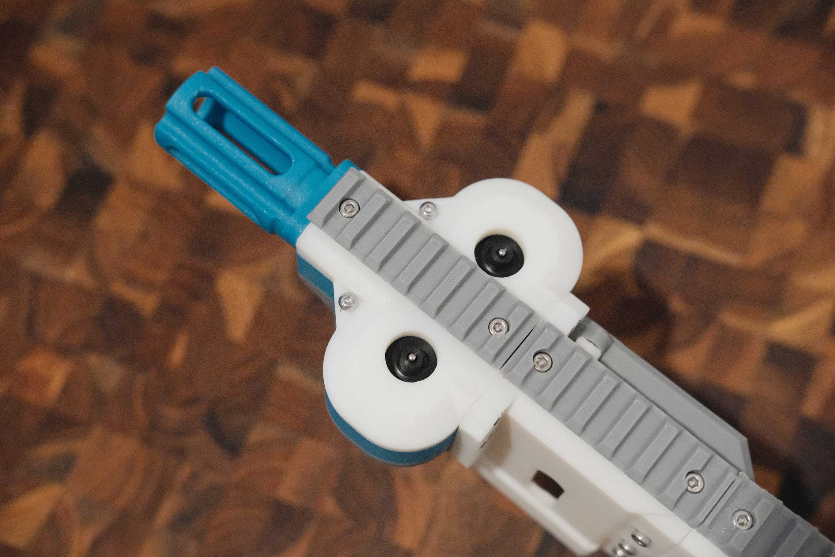
 Mount Flywheels
 Check Flywheels’ Alignment
When press-fitting the flywheels, get them as even as possible with the flywheels’ middles centered to the dart hole. Additionally, check to make sure they aren’t binding and don’t rub against any plastic as they turn.
 Install Flywheel Cover
- 2 x M3x8 SHCS
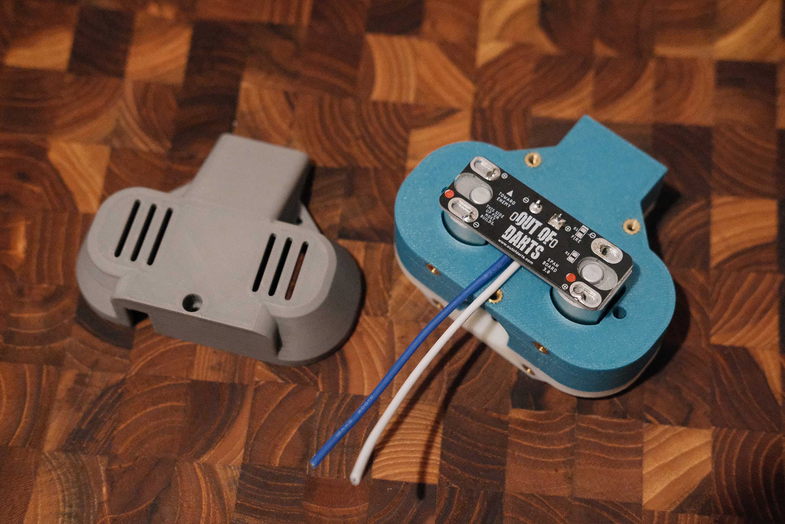
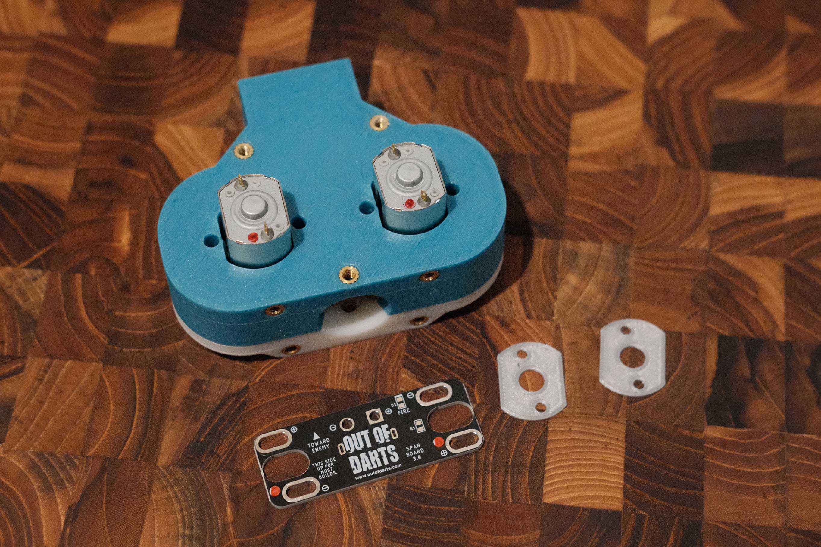 Out of Darts’ Motor Spanning Board
Out of Darts’ Motor Spanning Board makes wiring up the motors a bit easier. The PCB handles the inter-motor connections and you only have to deal with a pair of wires leading to the first XT60 female connector.
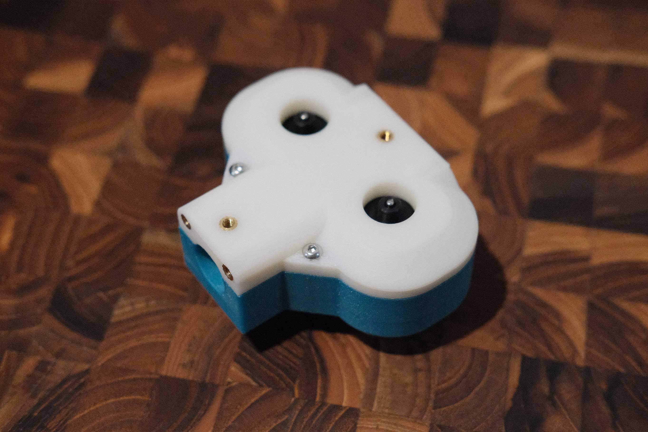
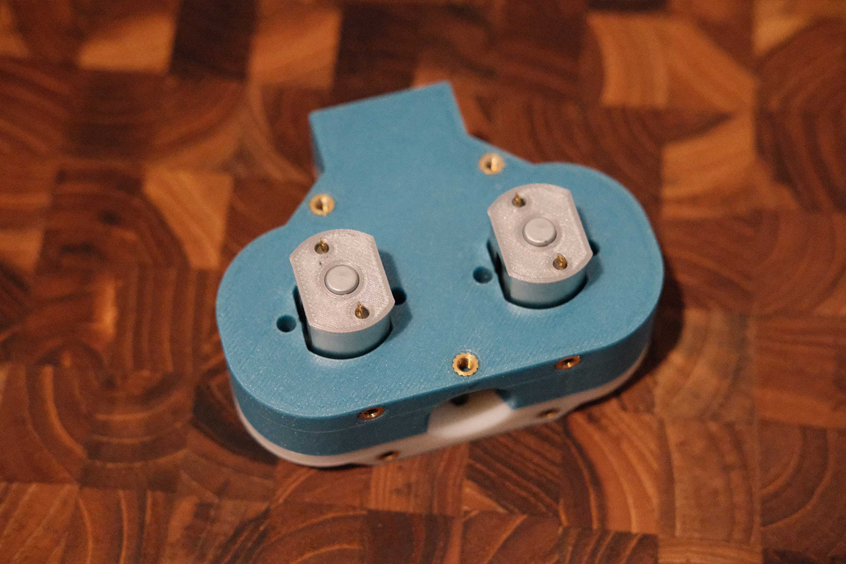 Place Motor Spacers
The motor spanning board comes with some printed spacers to give some clearance and prevent shorts. Place them like so.
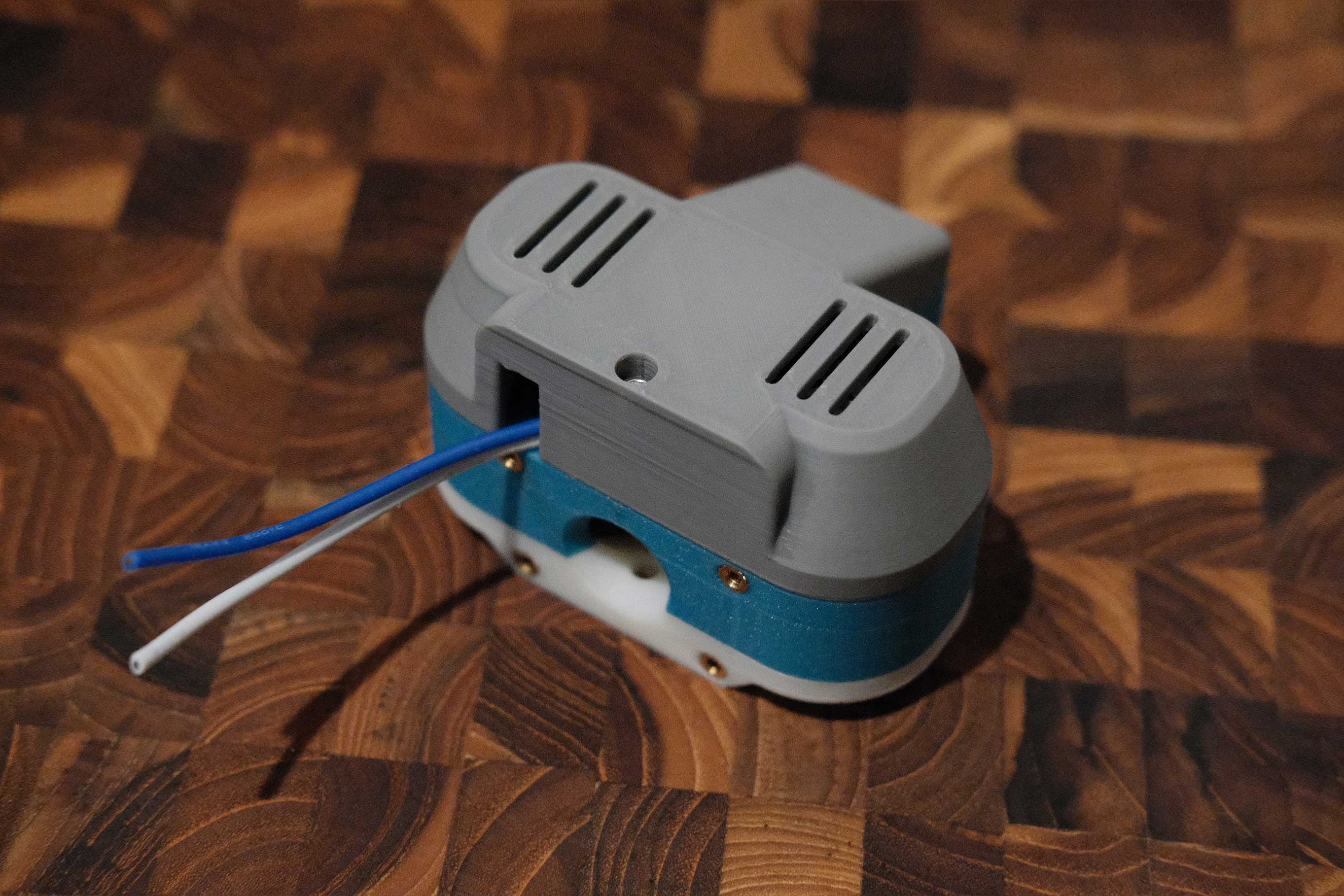
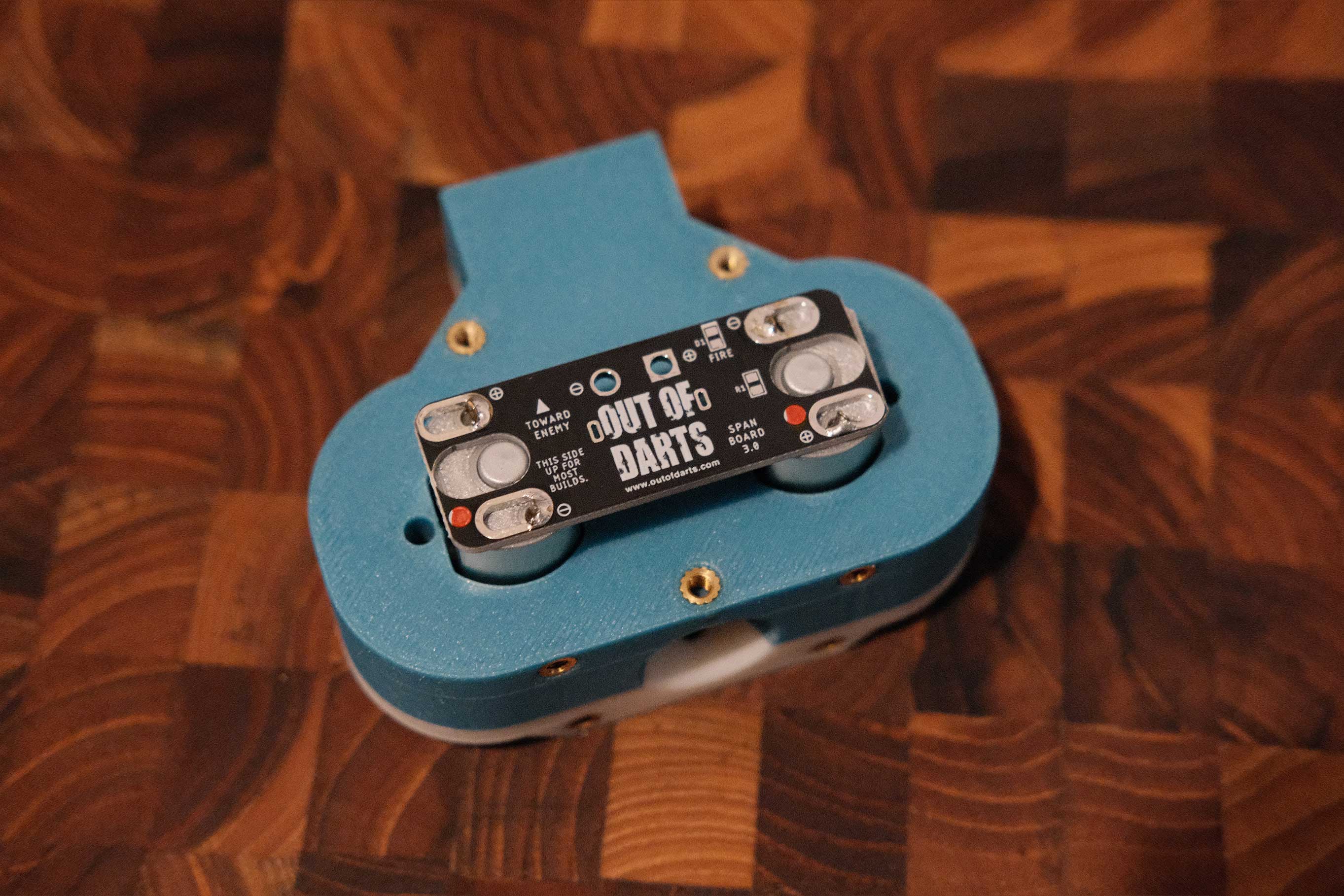 Spanning Board Soldered
 Solder Wires for XT60 Connector
 Install Motors’ Cover
- 2 x M3x8 SHCS
- 1 x M3x20 SHCS
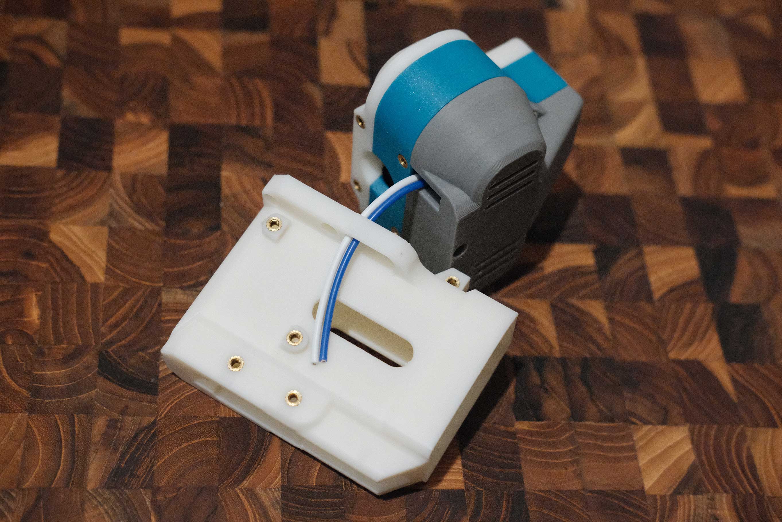 Check Wires Against Magwell for Length
Feed the wires through the magwell to get a feel for the length required. The XT60 connector here will sit underneath a wire cover.
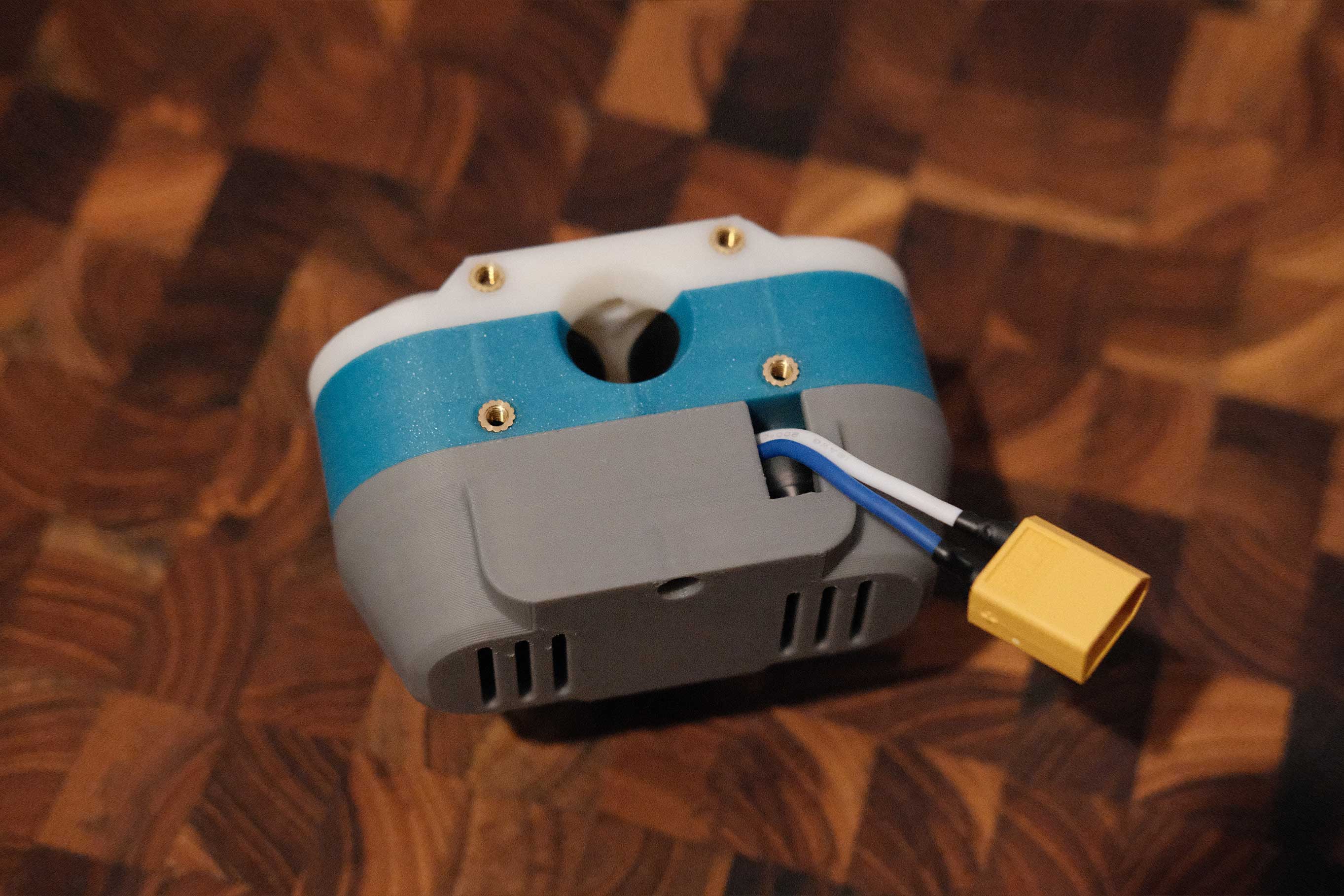 Solder and Heatshrink the XT60 Female Connector
Don’t forget to place the heatsinks on the wires before soldering to the XT60 female connector. In this particularly case, the motors were oriented per the PCB’s markings, but still ended spinning the wrong way, so I inverted the XT60 to correct it.
Magwell
 Attaching Magwell
- 4 x M3x8 SHCS
 Magwell attached
Grip
 Grip
Grip
 Grip with Switch Posts
Install the two screws that form the switch seating posts.
- 2 x M3x10 SHCS
 Switch Placement
The 21A switch sits like so.
 Required Wires
Positive wire (blue) has two runs; one from the motors to the switch, and one from the switch to the battery. We’ll be using NO and COM terminals to power the motors only when the trigger is pressed. Negative wire (white) goes directly from the motors to the battery.
 Finish the Motors’ XT60 Connector
Solder the wires to the XT60 male connector, connect it to the motors, then feed the wires through the top cover.
 Solder the 21A Switch
Solder the other end of the motors-to-switch positive wire and one end of the switch-to-battery wire to the NO and COM terminals of the switch. It does not matter which wire goes to NO and COM.
 Install Switch Trigger and Tuck Wires
Assemble and install the switch trigger. Apply a bit of silicone grease to smoothen the action. Wires will tuck like so.
- 1 x M3x6 SHCS
 Install the Pusher
Install the pusher with the teeth on the far side and closer to the rear of the grip. Apply a bit of silicone to the sides of the pusher to smoothen the action.
 Install the Trigger
Install the trigger with the spring. Depending on print quality and spring strength, you may need a second spring to ensure that the trigger and pusher returns to the original positions. Apply a bit of silicone grease to area around the post and spring to smoothen the action.
 Install the Toothed Gear
Install the toothed gear and line up the center hole with the receiving hole in the grip. Apply a bit of silicone grease to the faces of the gear to smoothen the action.
 Install Grip Cover and Toothed Gear Shaft
Secure the grip cover with an M3 screw, and insert the 2mm shaft through the cover, toothed gear, and grip frame.
- 1 x M3x6 SHCS
 Close Top Cover
Close up the top cover. This part is fiddly. Wires should stay tucked behind the toothed gear and not impede the gear rotation. There’s a notch in the cover to accommodate the shaft.
 Secure Mag Release
Secure the mag release switch with an M3 screw.
- 1 x M3x16 SHCS
 Install Spring and Connect Magwell with Grip
Place the mag release spring between the magrelease switch and grip frame, and insert the grip into the magwell. This is a good opportunity to test the trigger action. The trigger and pusher should extend and return with no sticking. Watching the action from the bottom of the magwell, you should see the pusher extend forward and retract all the way. If the pusher does not retract fully, it will prevent darts from feeding properly.
 Install Magwell Wire Cover
Install the wire cover over the XT60 connector.
- 2 x M3x6 SHCS
 Install Right Scale
Install the right scale.
- 2 x M3x6 SHCS
 Install Left Scale
Install the left scale.
- 2 x M3x6 SHCS
 Install Remaining Screws
Secure the magwell, grip, and top cover with through screws.
- 4 x M3x25 SHCS
Stock
 Check Wire Length
The wires need to feed through the buffer tube with a extra few inches to make it easy to handle the battery.
 Finish XT60 Connector
Add heatshrink and solder the wires to an XT60 female connector.
 Stock Parts
 Sling Mount and Buttplate Hook
Attach the sling mount to the top of the buffer tube (my printed part has no sling mount), and install the buttplate hook.
- 2 x M3x12 SHCS
- 1 x M3x8 SHCS
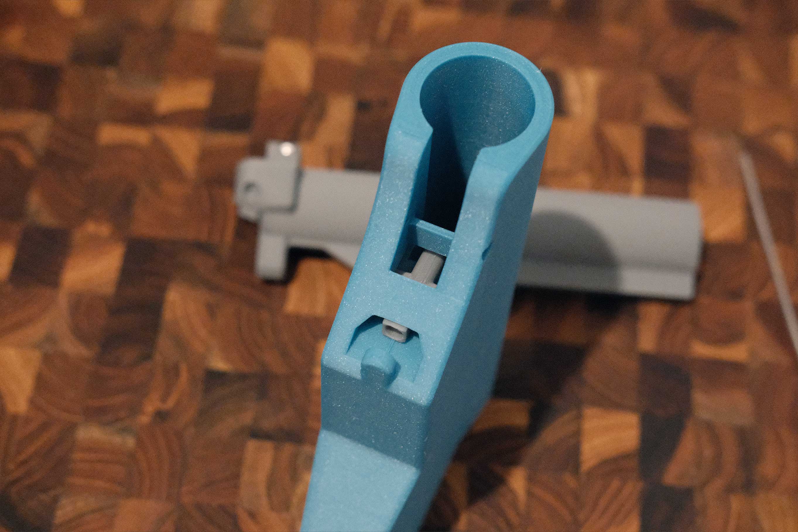 Insert Locking Pin
Insert the locking pin into the stock.
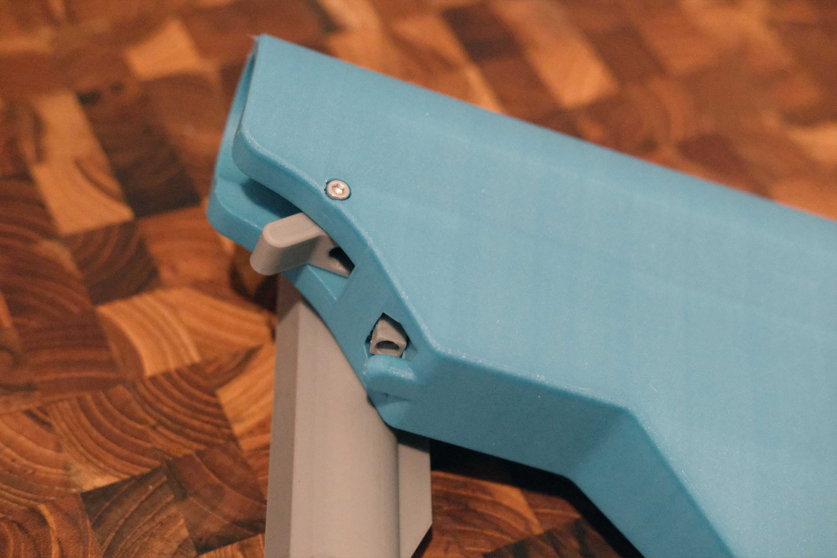 Secure Lock Release
Install the lock release.
- 1 x M3x20 SHCS
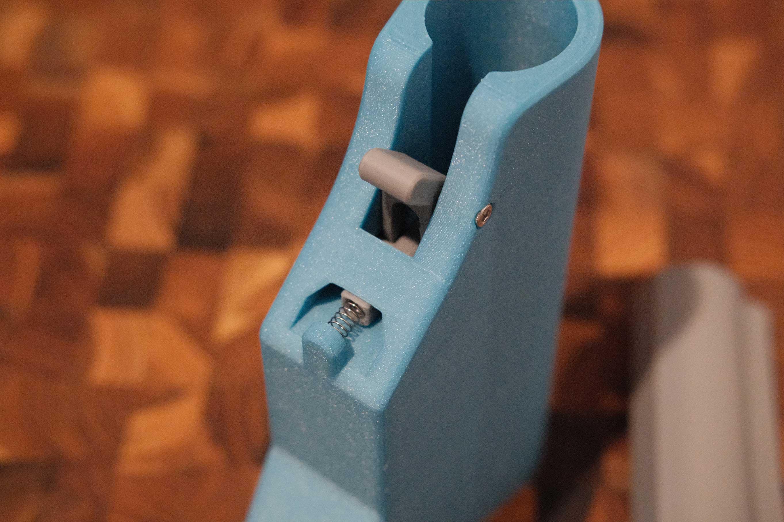 Add Spring
Add the spring. This spring needs to be strong enough to keep tension on the locking pin and prevent the stock from collapsing during use.
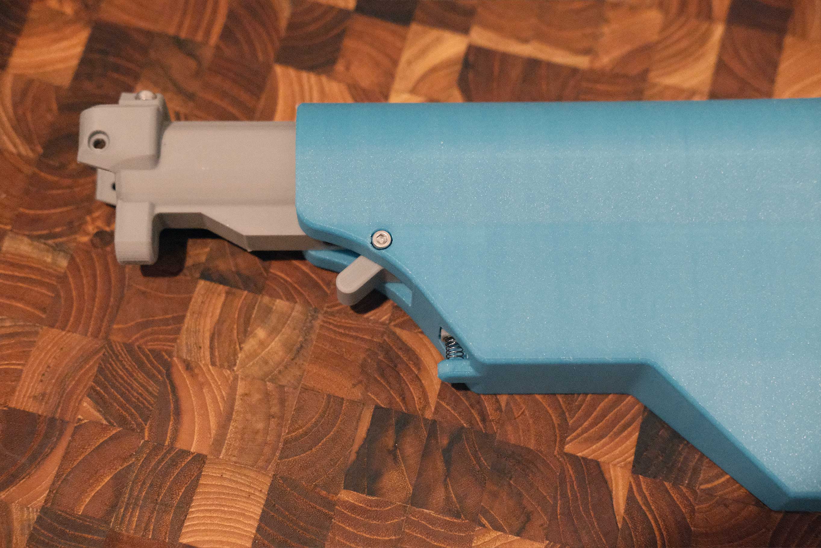 Insert Buffer Tube
Insert the buffer tube.
 Feed XT60 Connector
Feed the XT60 connector through the buffer tube. It should stick out just a bit.
 Attach Stock to Grip
Attach the stock to the grip. There’s a screw on each side and two on the rear.
- 2 x M3x8 SHCS
- 2 x M3x12 SHCS
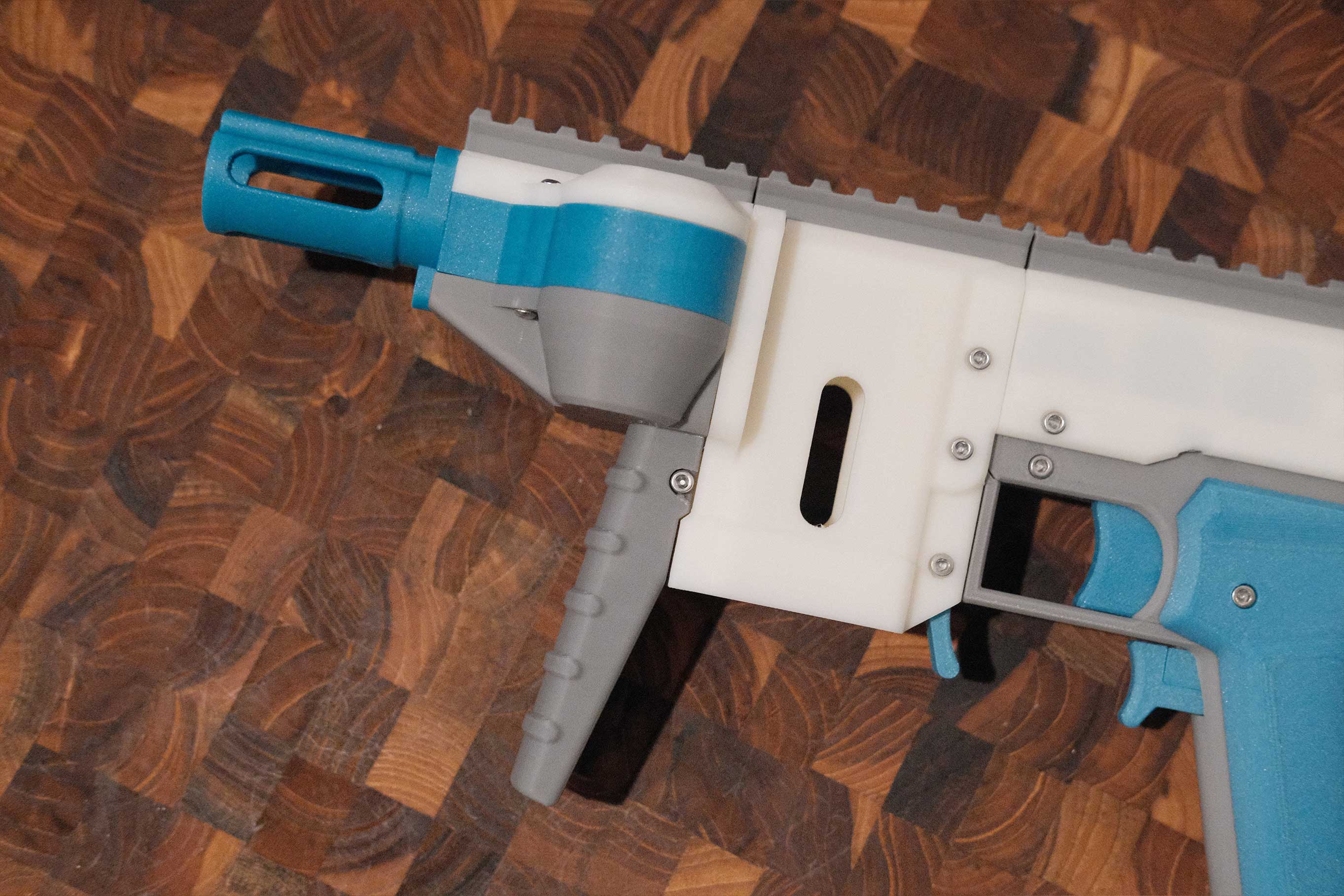
 Flash Hider and Picatinny Rails
Attach the flash hider and picatinny rails.
- 9 x M3x8 SHCS
 Flash Hider and Picatinny Rails
Should look like this.
 Check Picatinny Spacing
Double check the picatinny pattern spacing.
 Install Front Grip
Install your front grip of choice.
- 2 x M3x8 SHCS
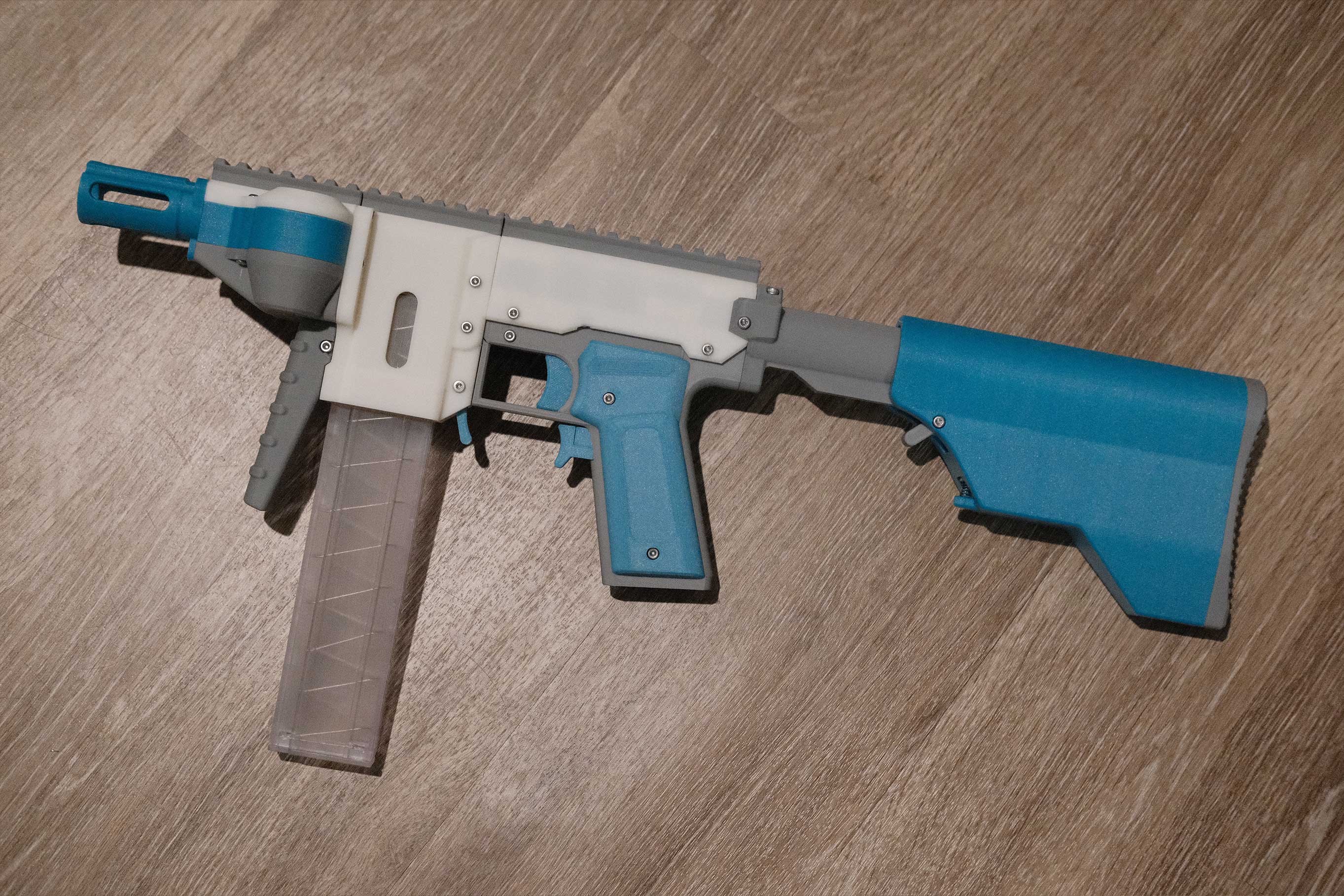 Complete
Your Gryphon/Gryphle0n is complete!