Lynx
Table of contents
Introduction
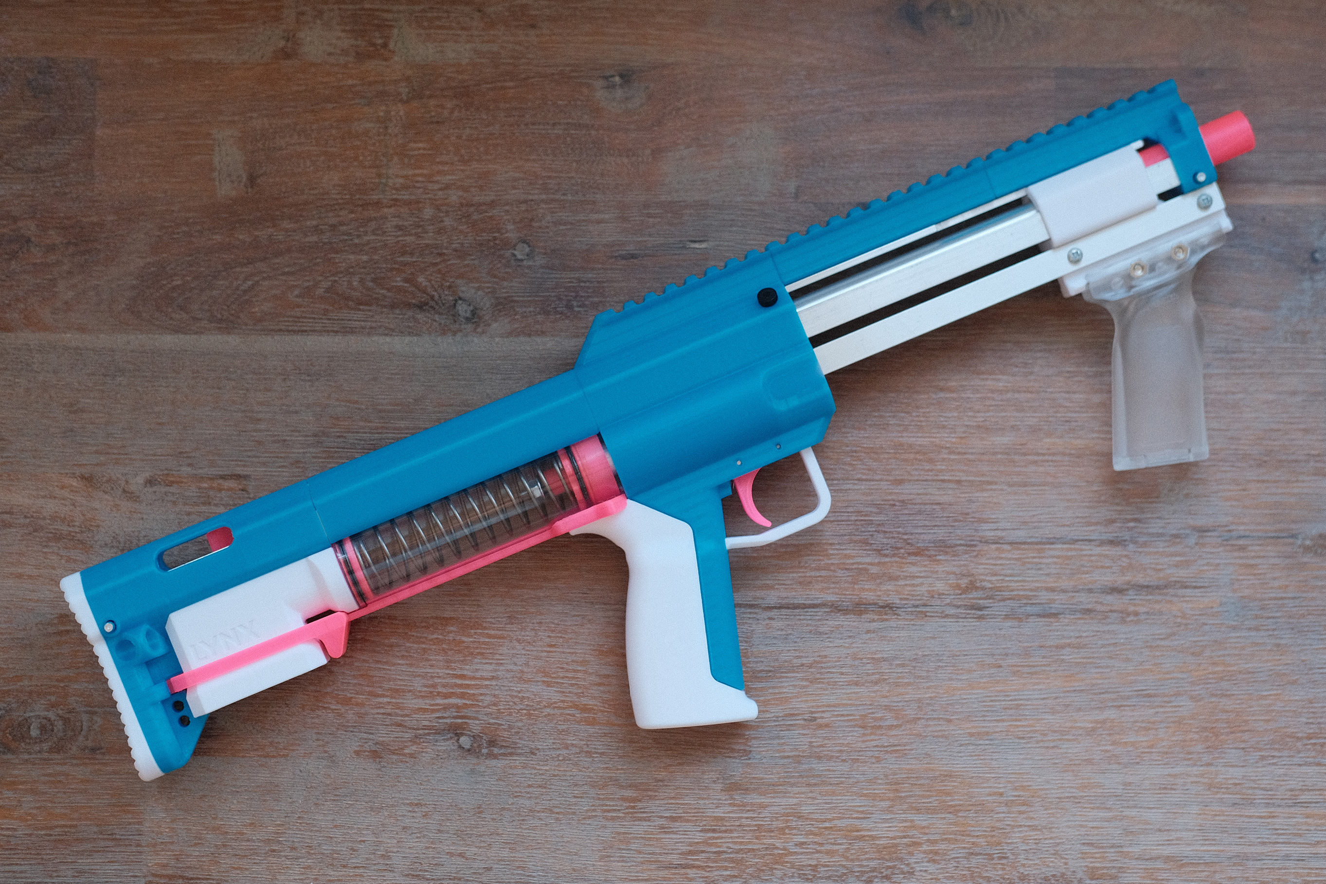
The Lynx is an open-source spring-powered blaster designed by Orion Blasters. CAD file and STL files are available here, and hardware kits are available here.
Features
(Pulled from the Orion Blasters’ Lynx page)
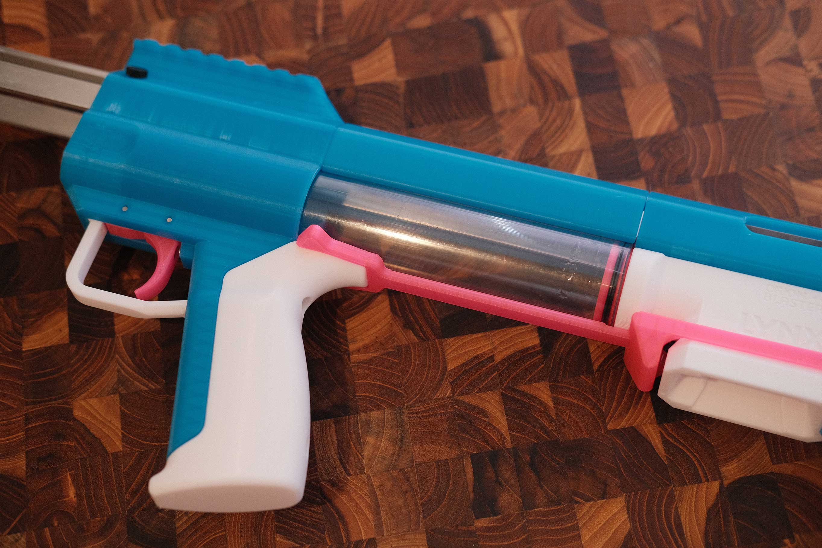
The Lynx is a Bullpup Mag-Fed Pump-Action Homemade Blaster for half length darts designed for the sport of Competitive Dart Tag. It features closed bolt mag swaps, slam-fire, is compatible with all longshot and talon claw springs, and can be completely disassembled without tools.
 Lynx
Lynx
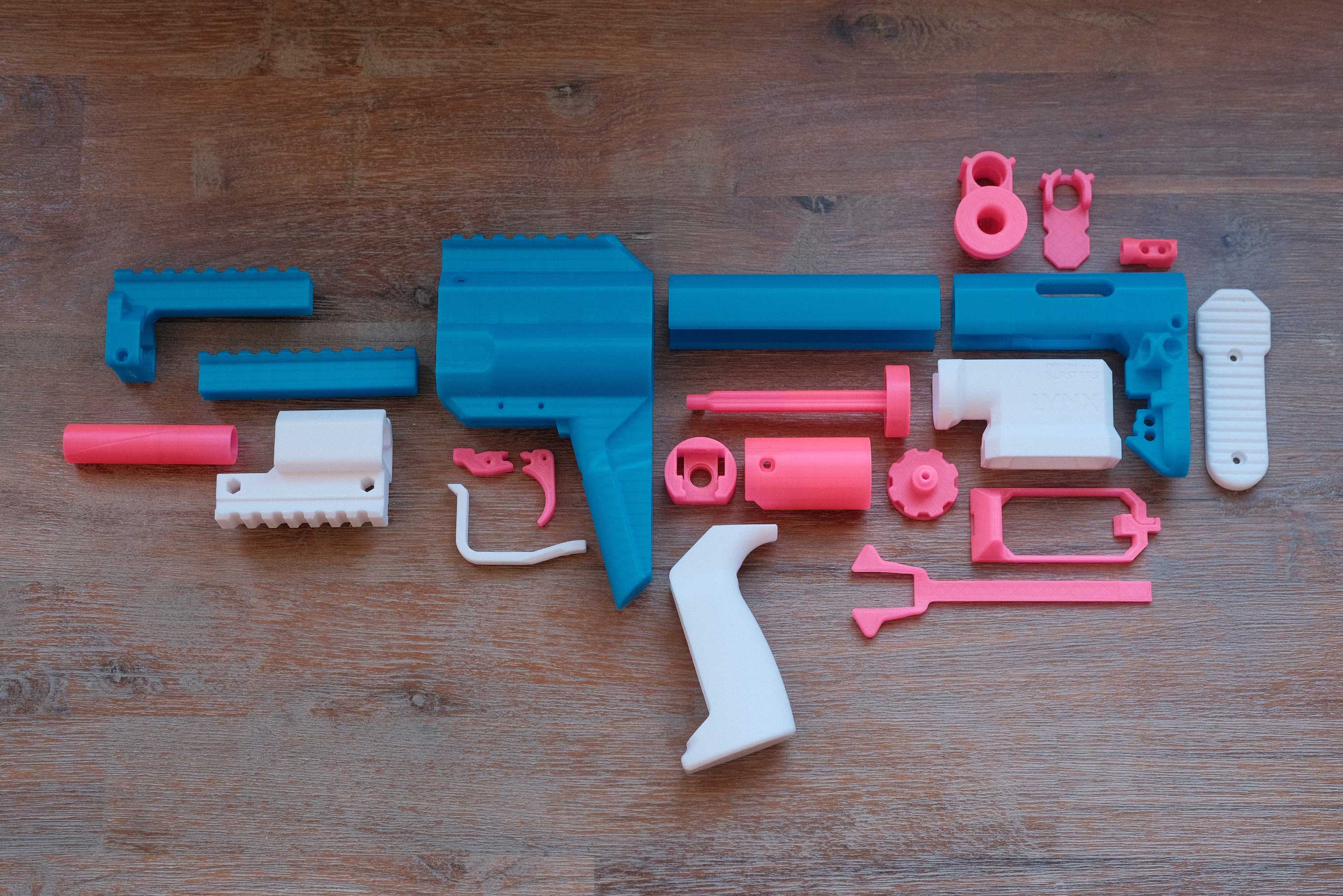
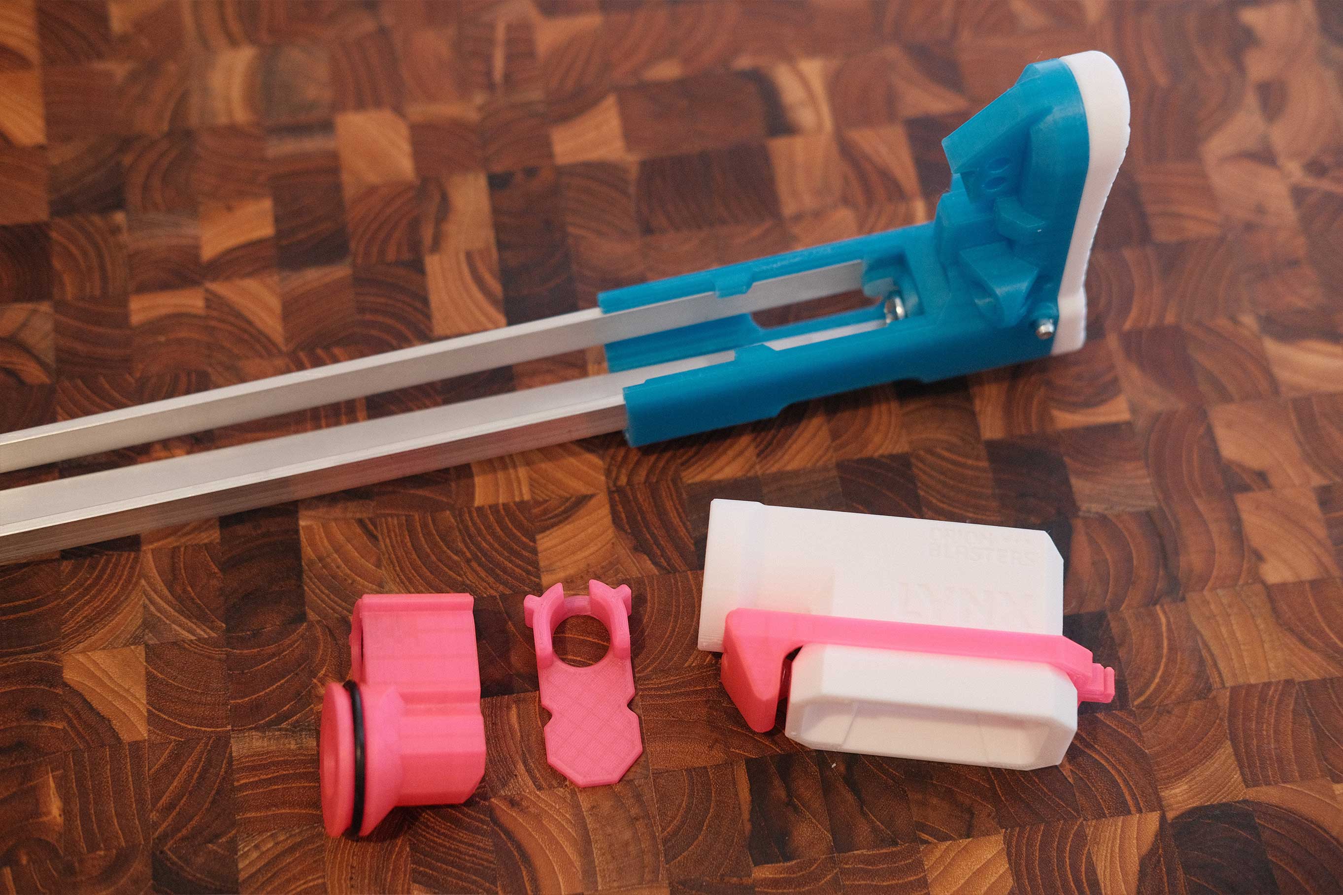
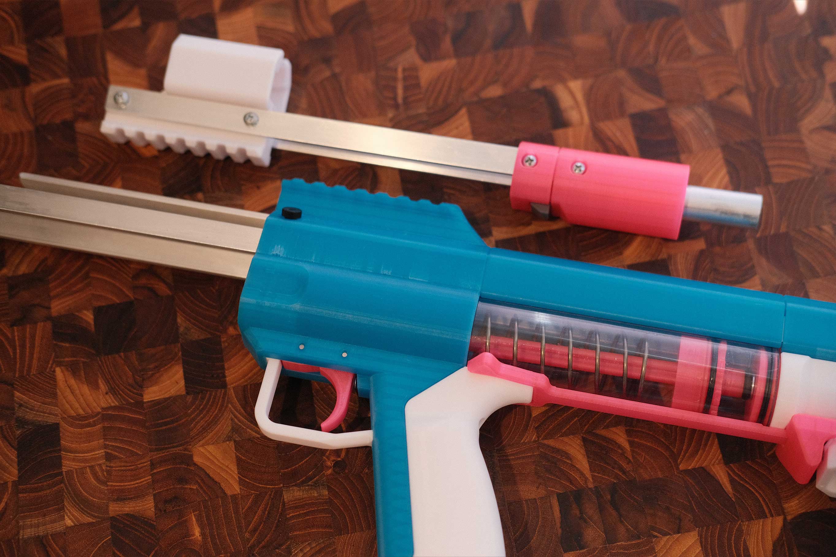
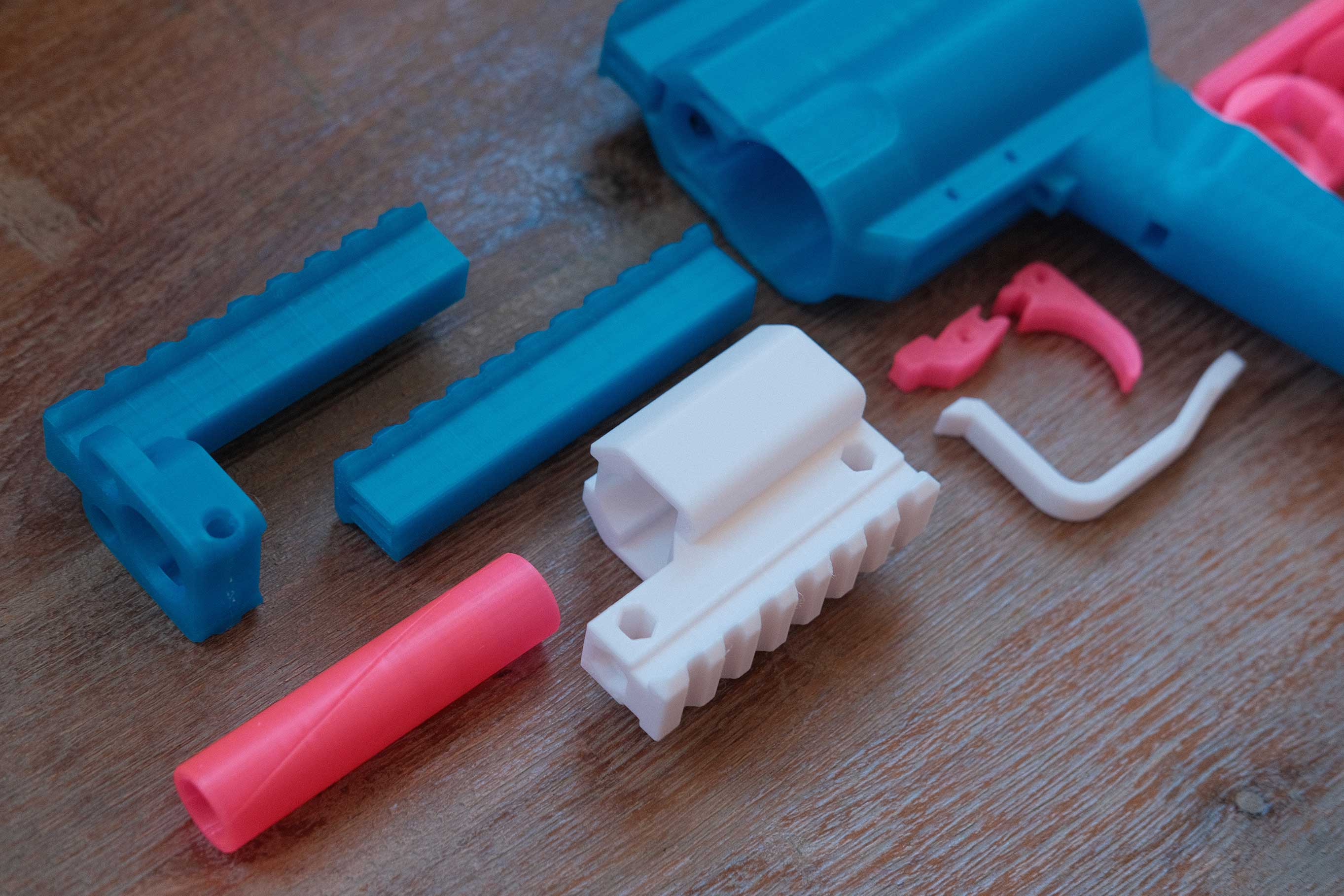 Lynx - Front Parts
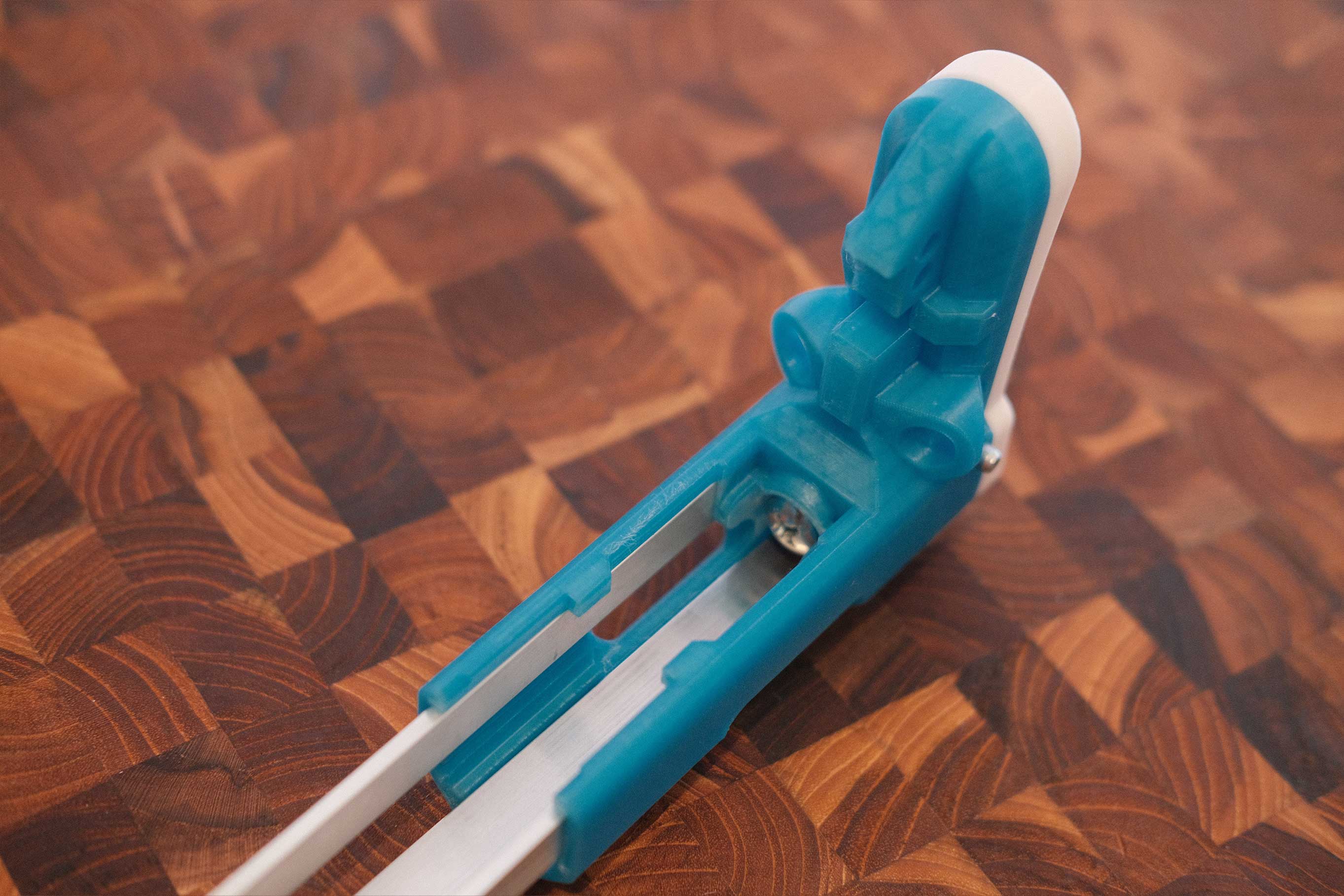
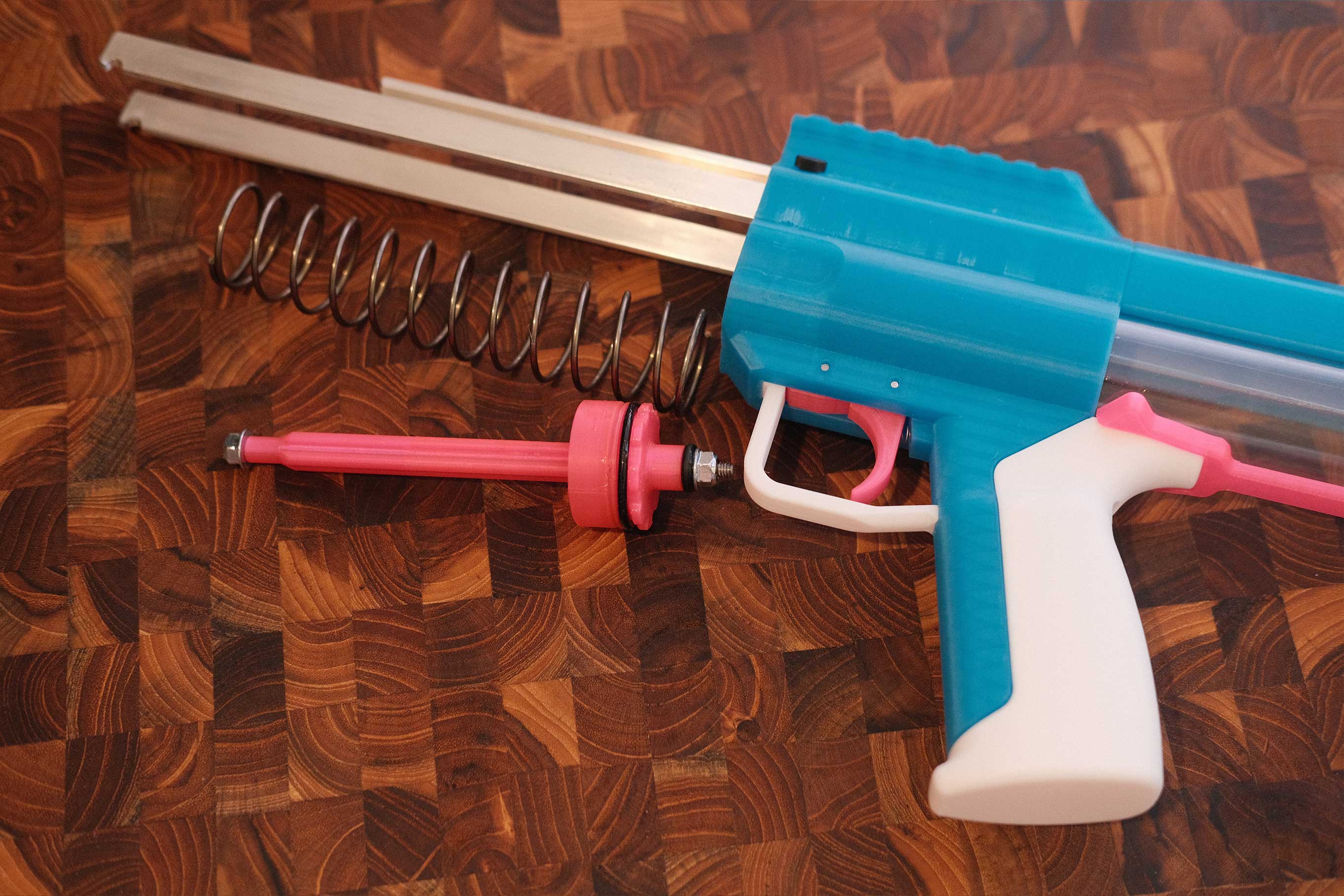
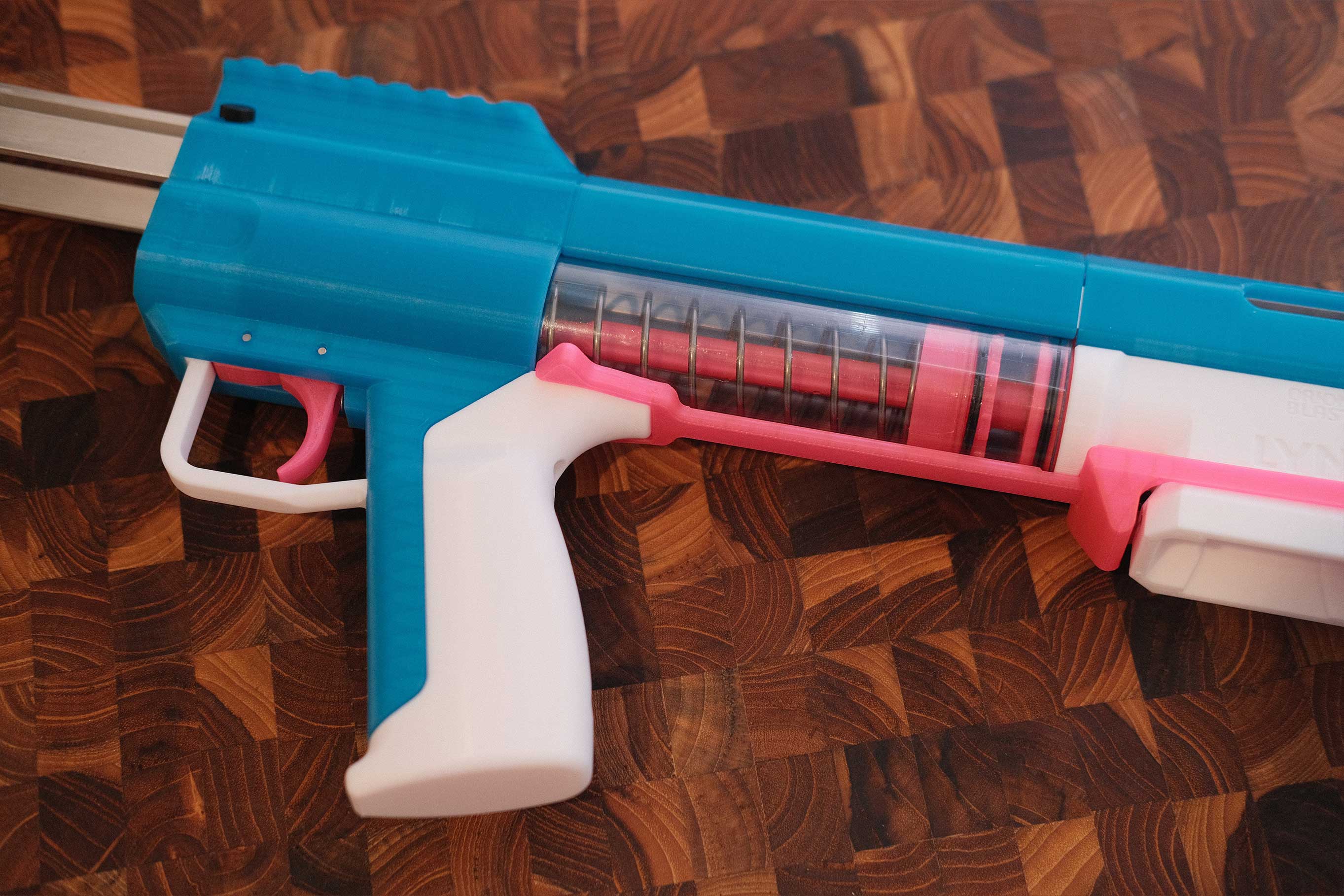
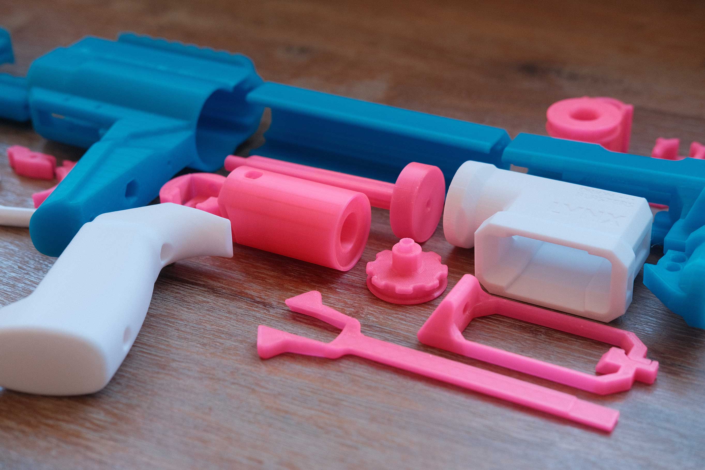 Lynx - Internals
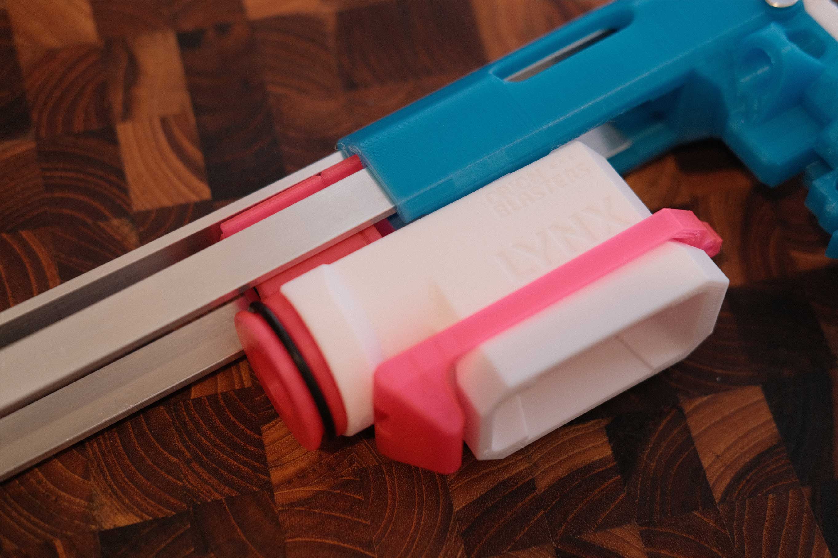
![]() Lynx - Branding
Lynx - Branding
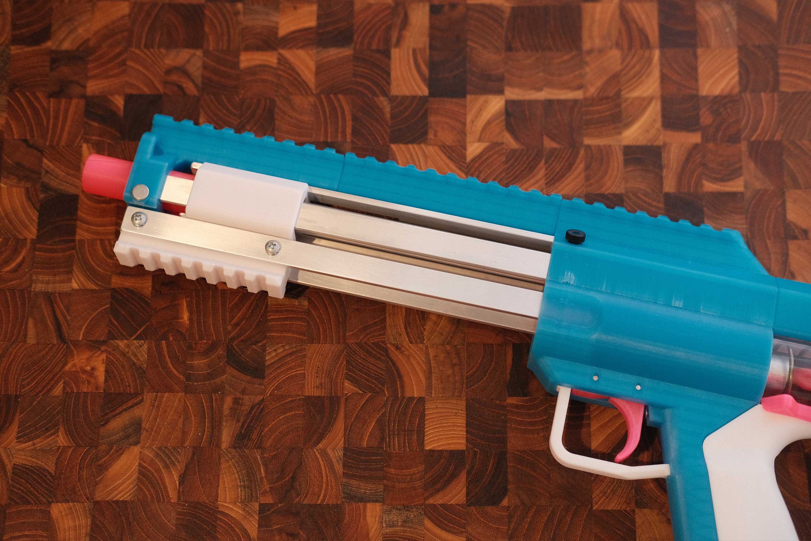
 Lynx - Top View
Build Guide
Plunger
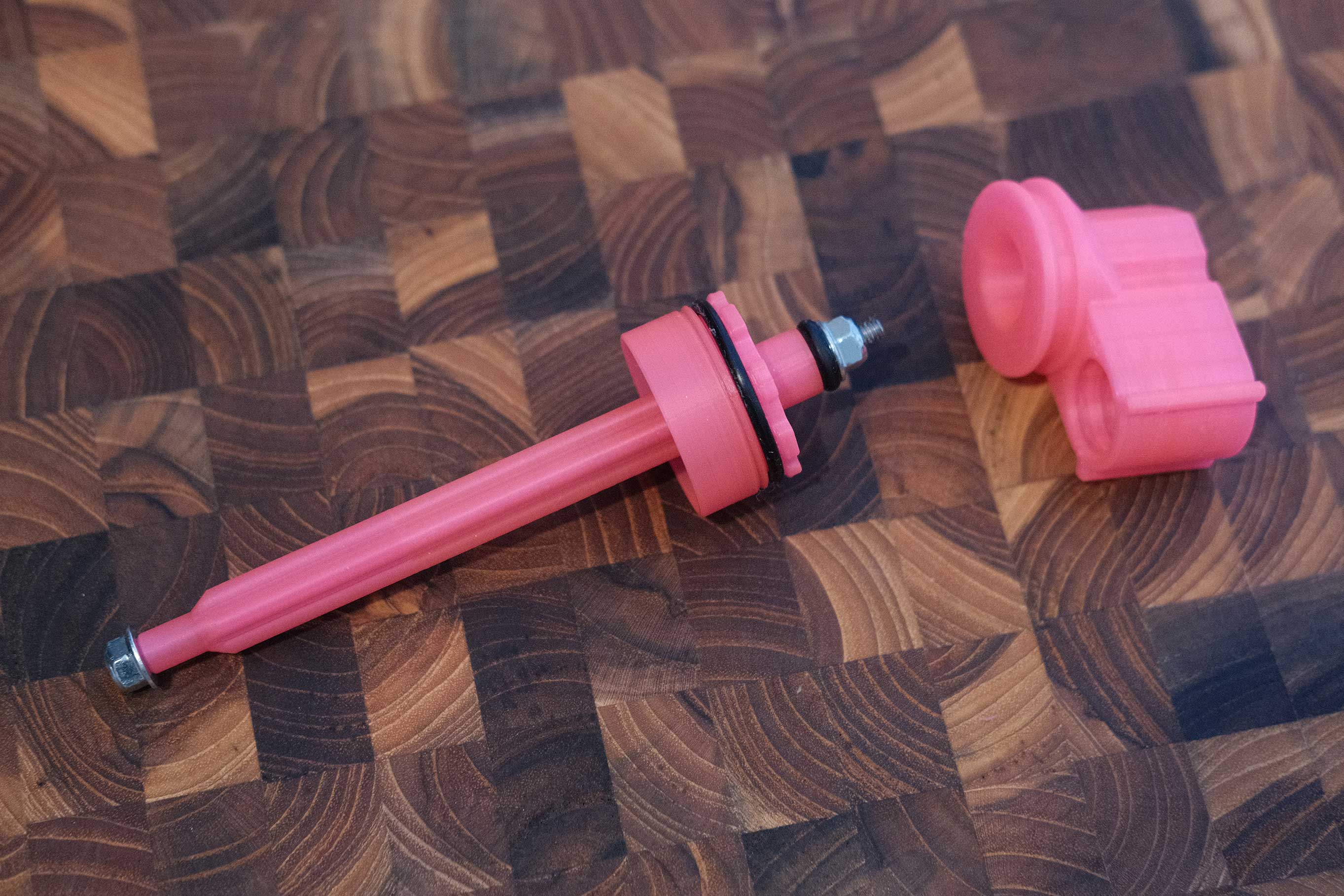
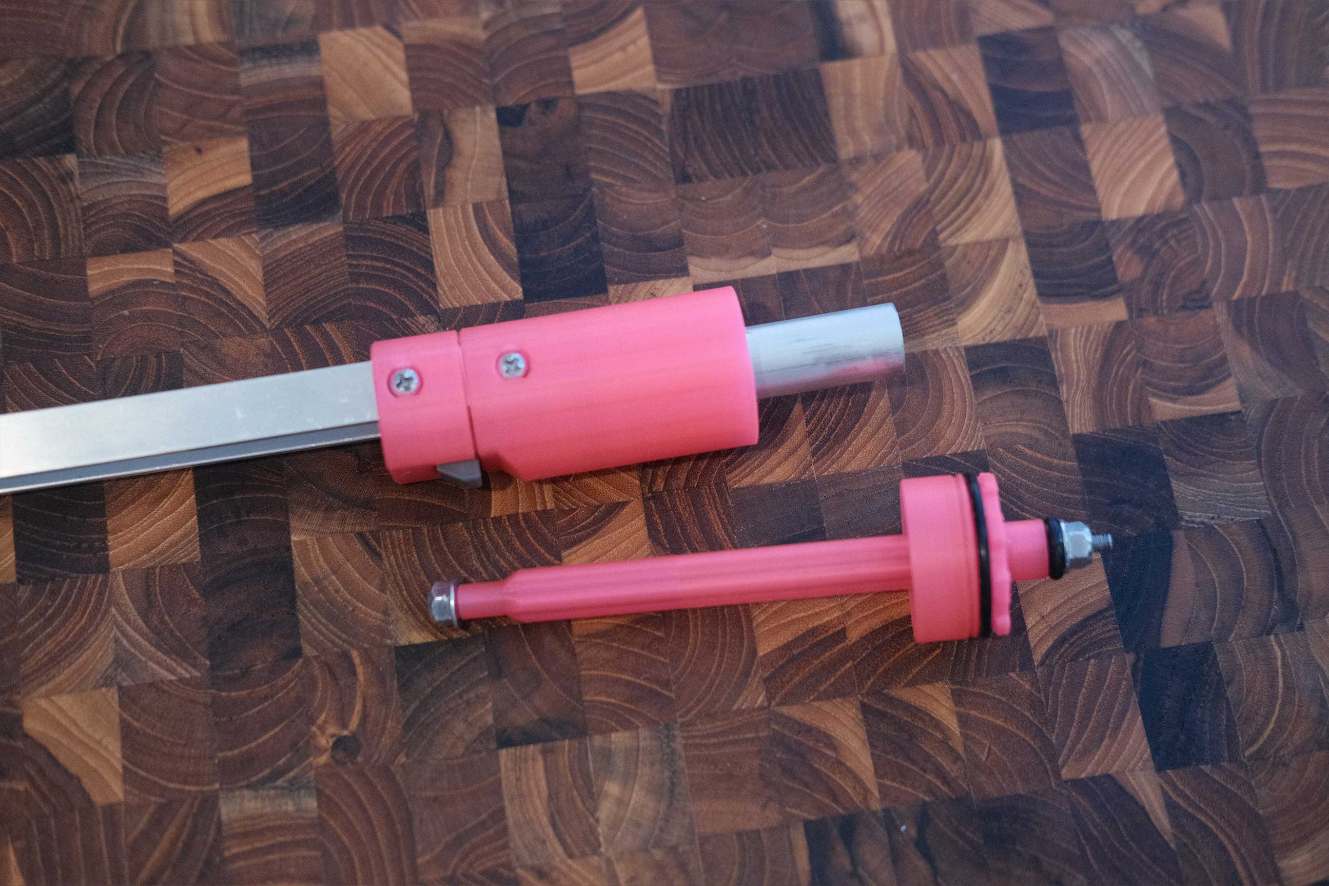
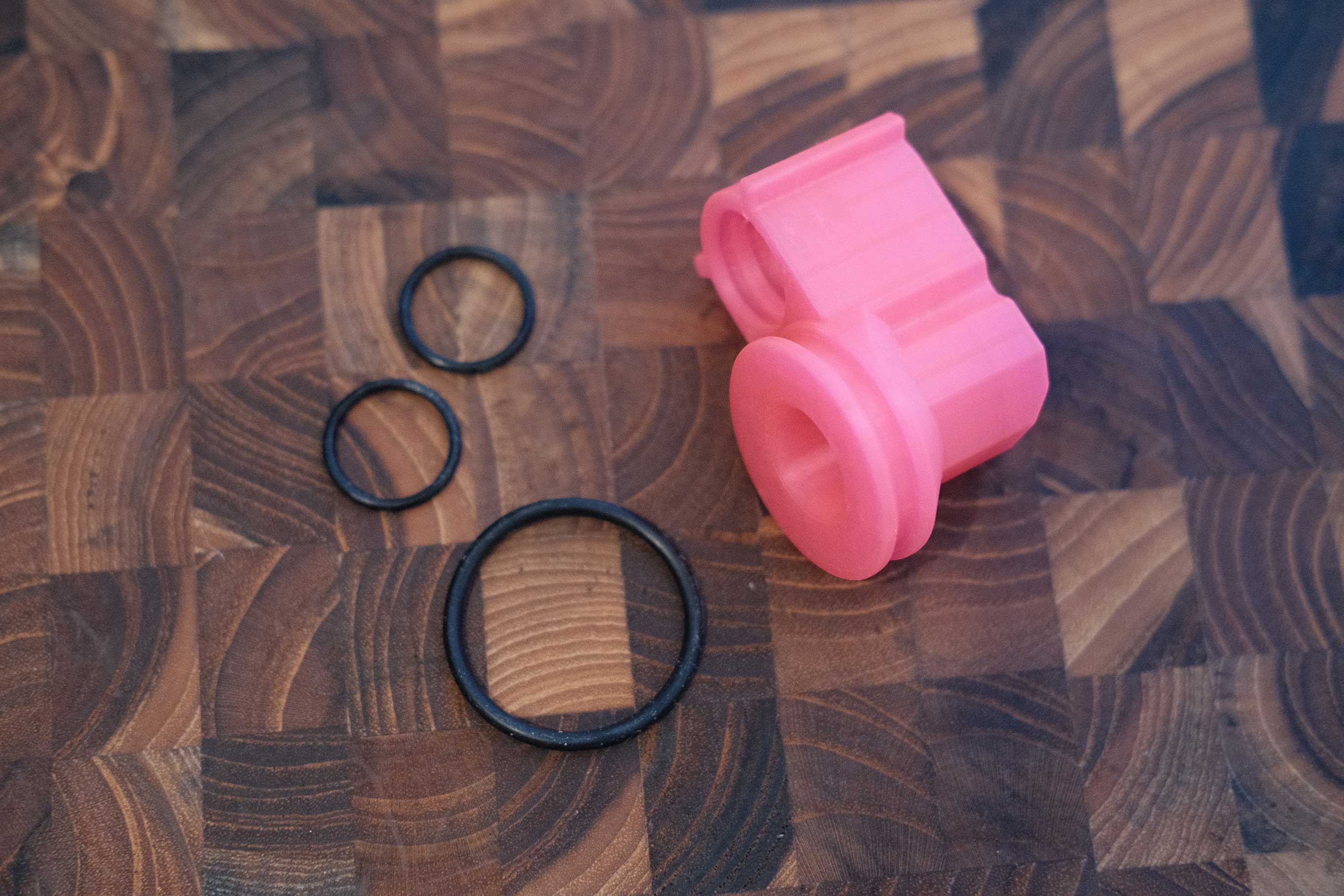
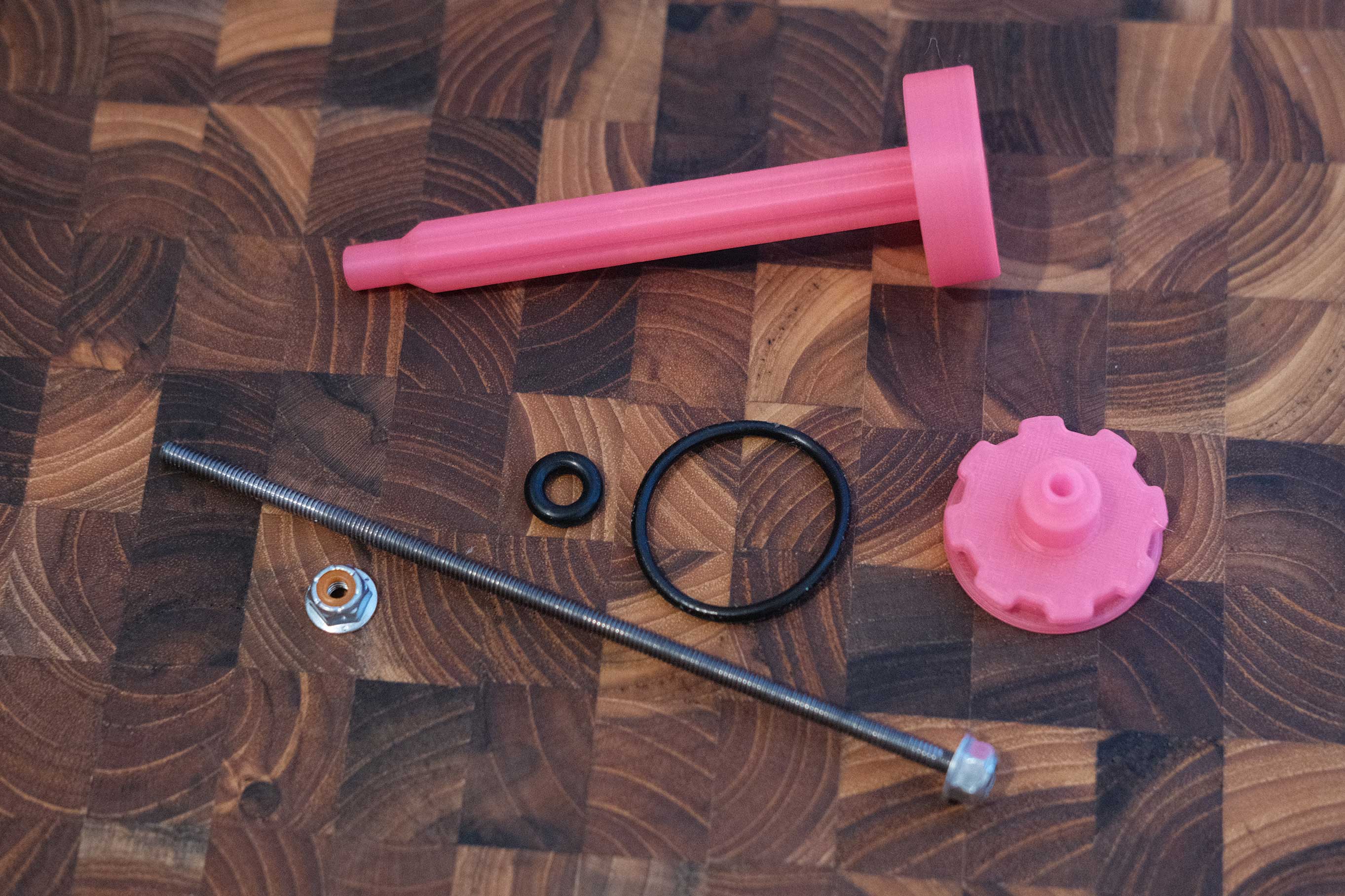 Plunger Parts
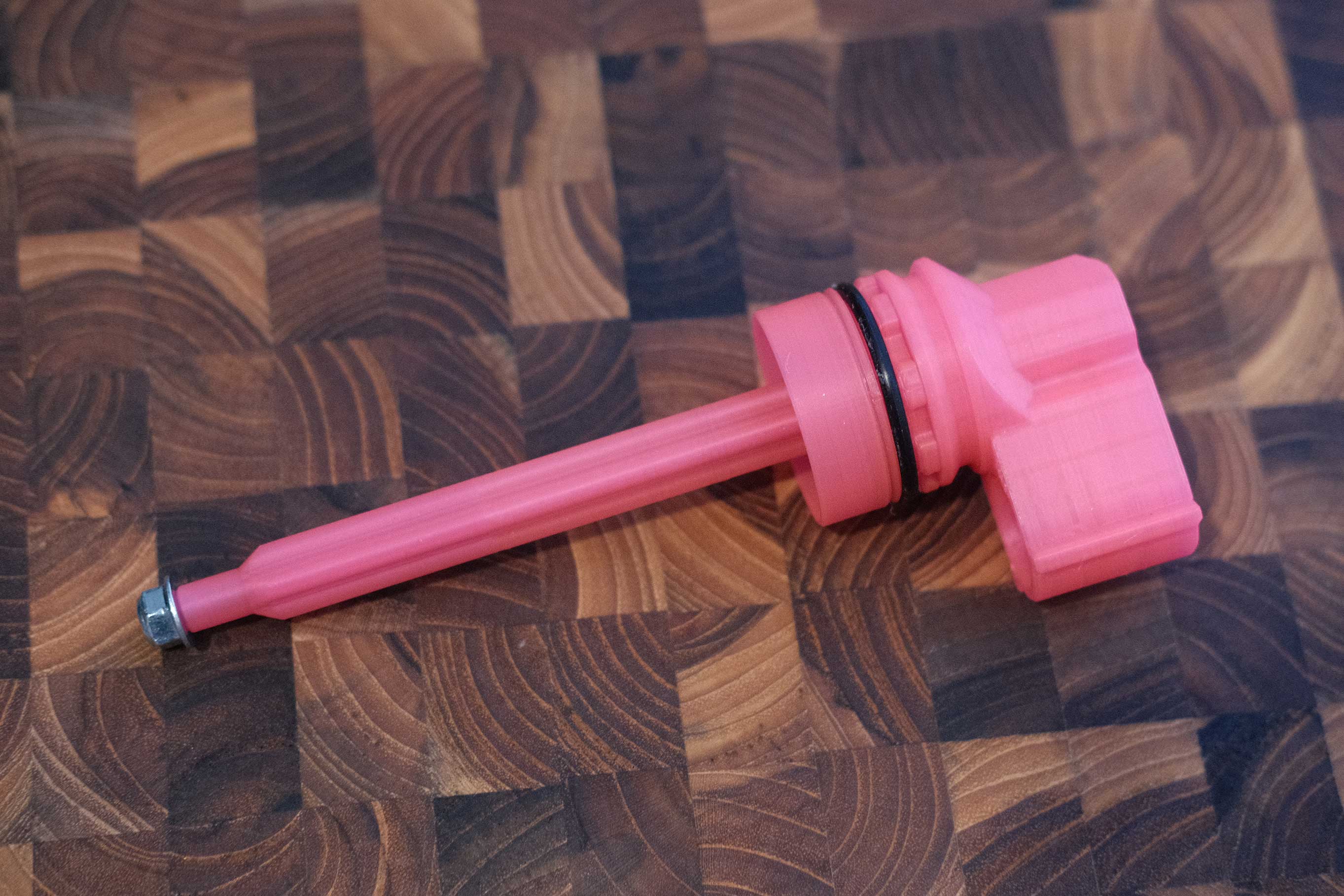
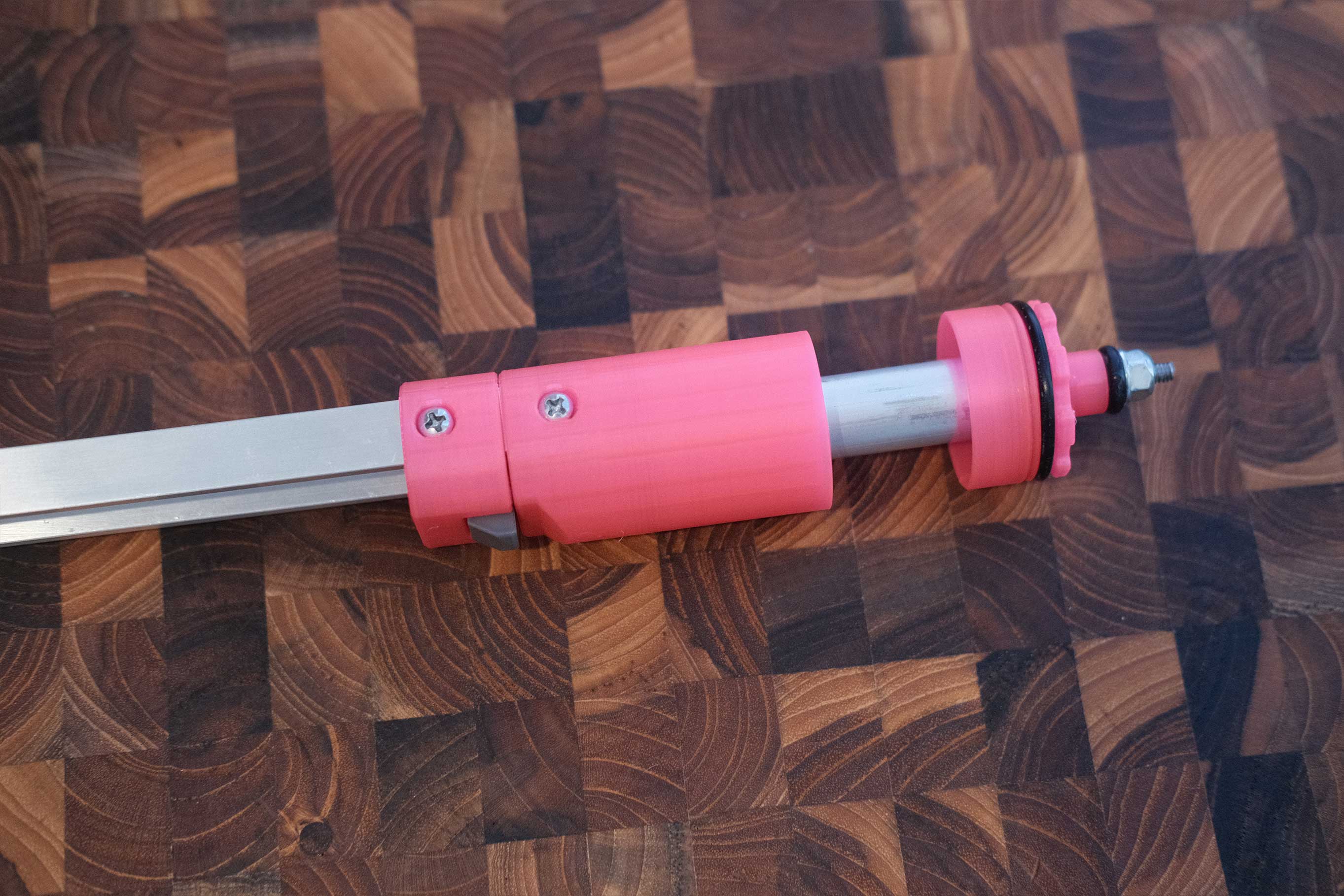
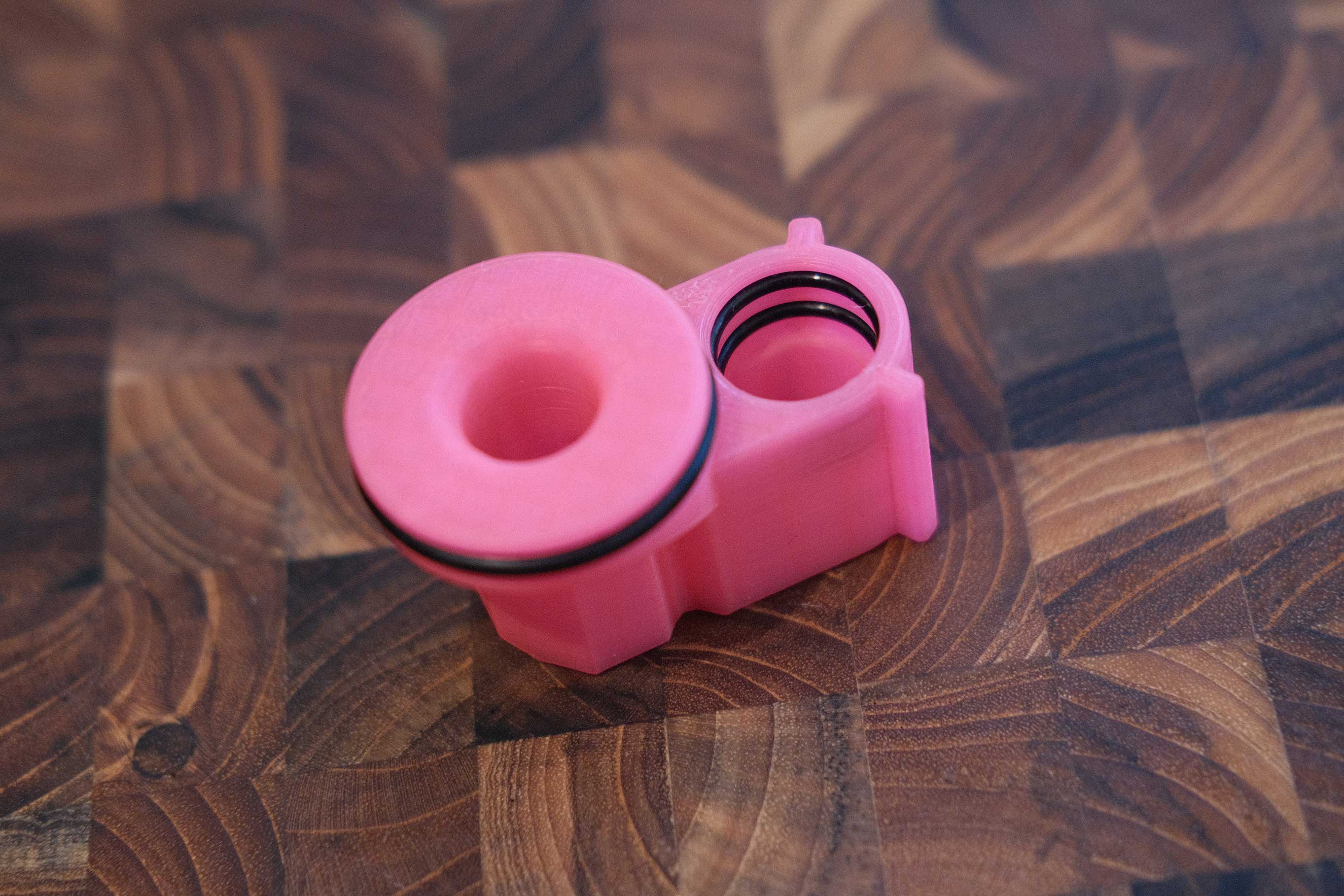
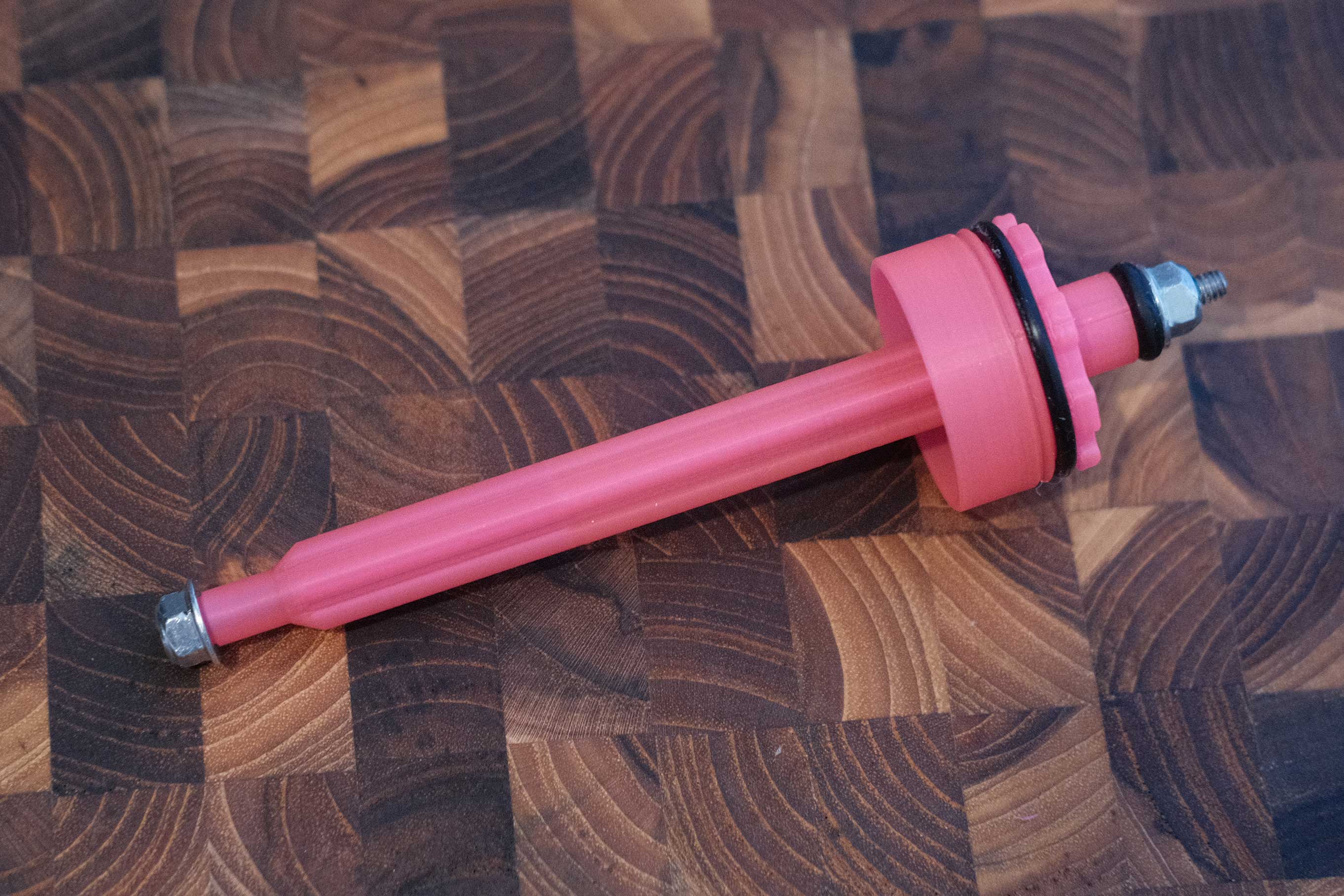 Plunger Assembled
 Test Fitment with Turnaround
The o-ring nut controls how squished the o-ring is. You want it squished enough to get a good seal with the turnaround, but not so much that it’s hard to insert.
 Test Fitment with Turnaround
Stock
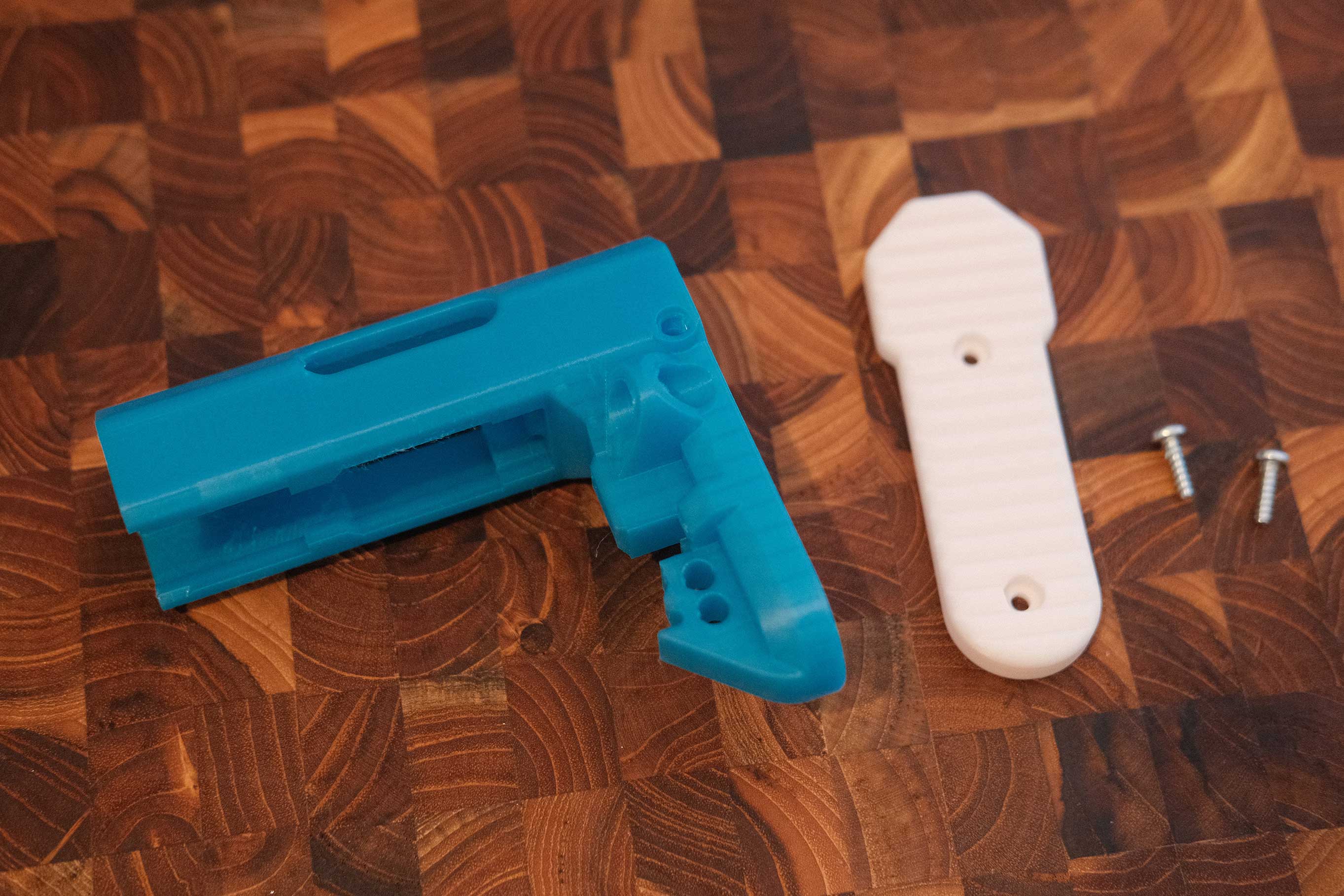 Stock Parts
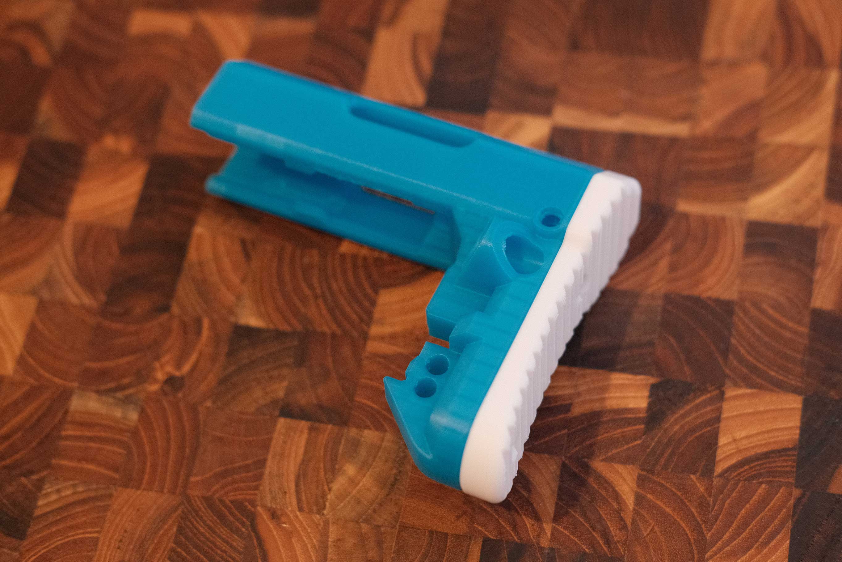 Stock Assembled
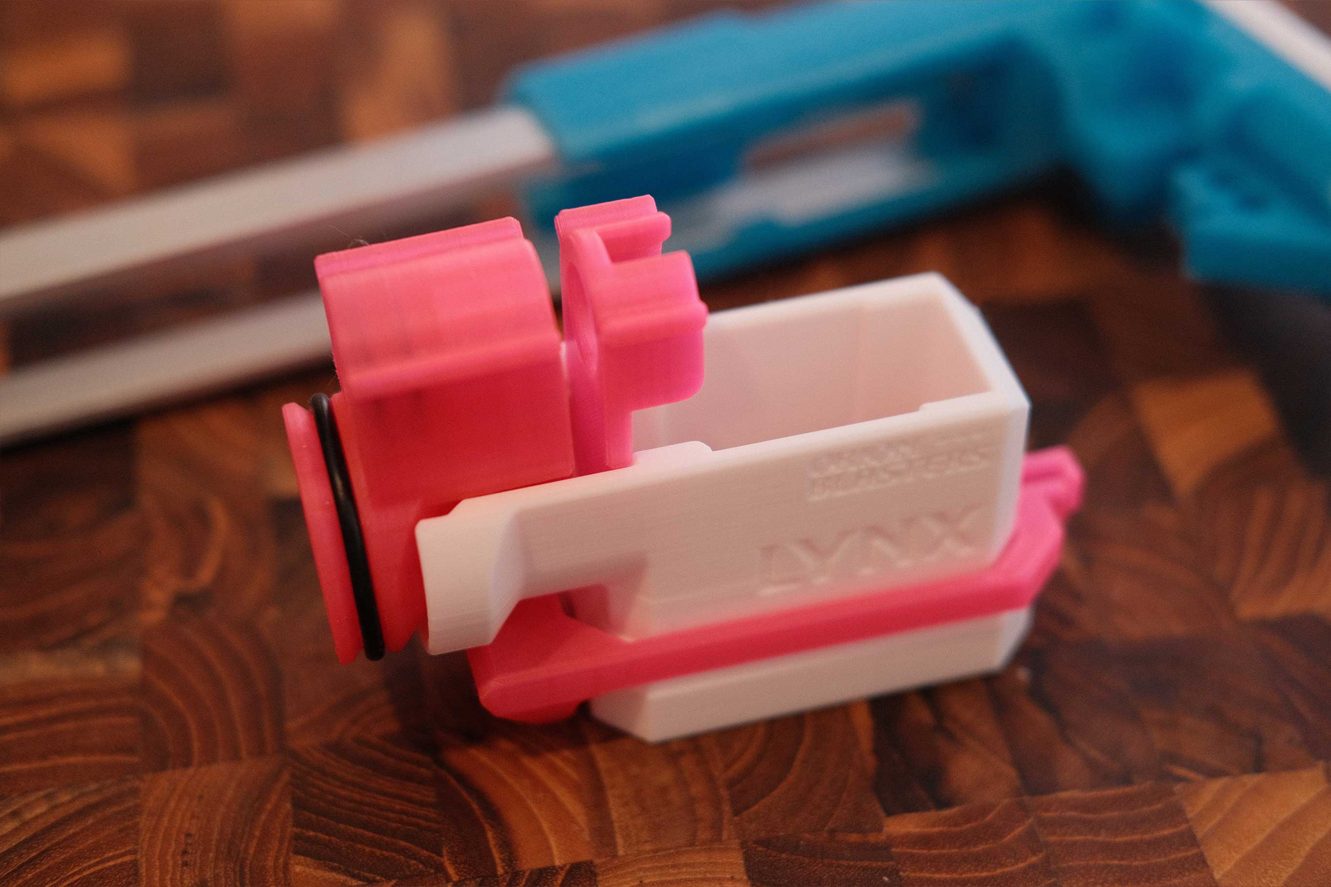
Magwell
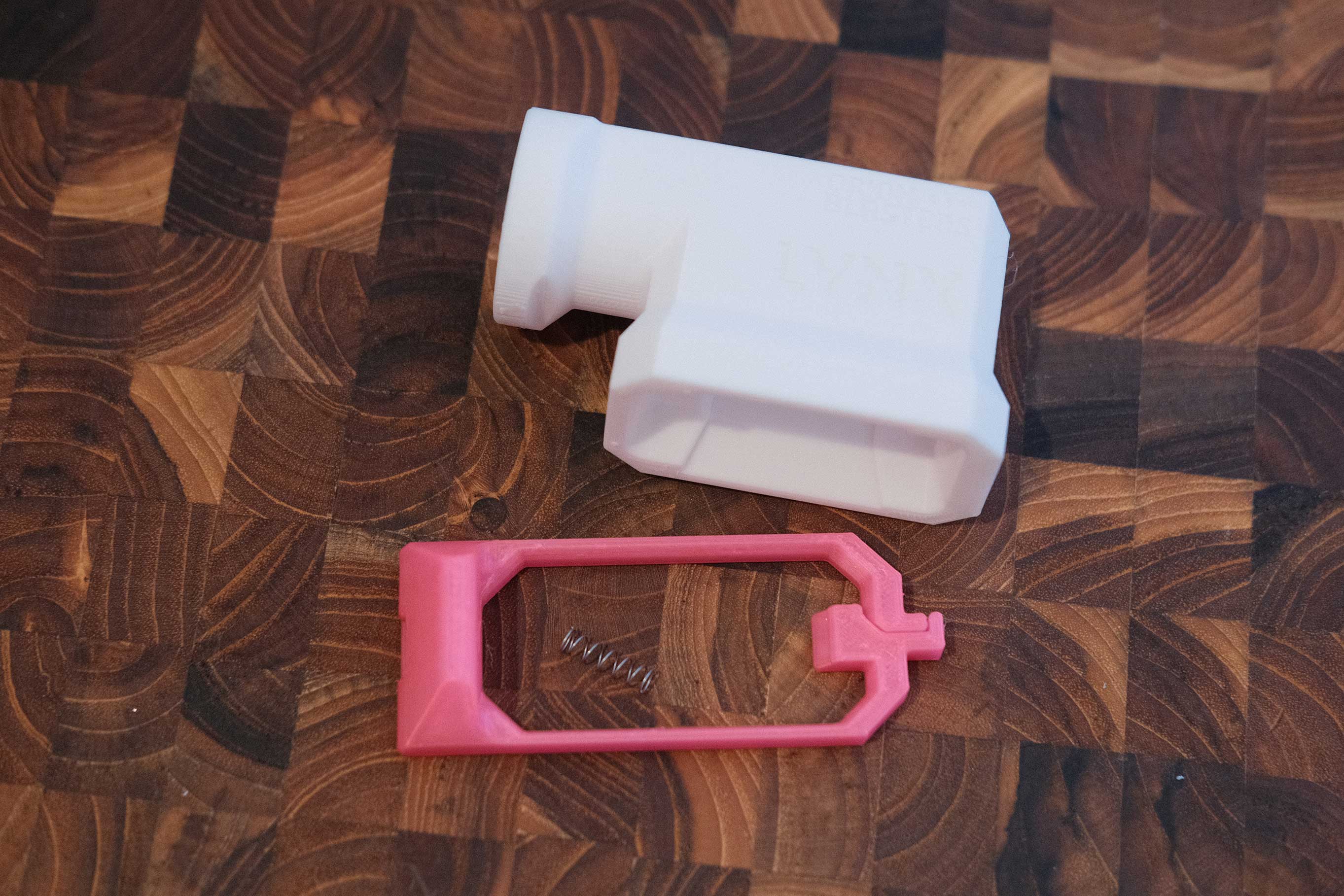 Magwell Parts
It’s a bit of a balancing act to get the spring seated while wrapping the release arms around the magwell, but it’s doable.
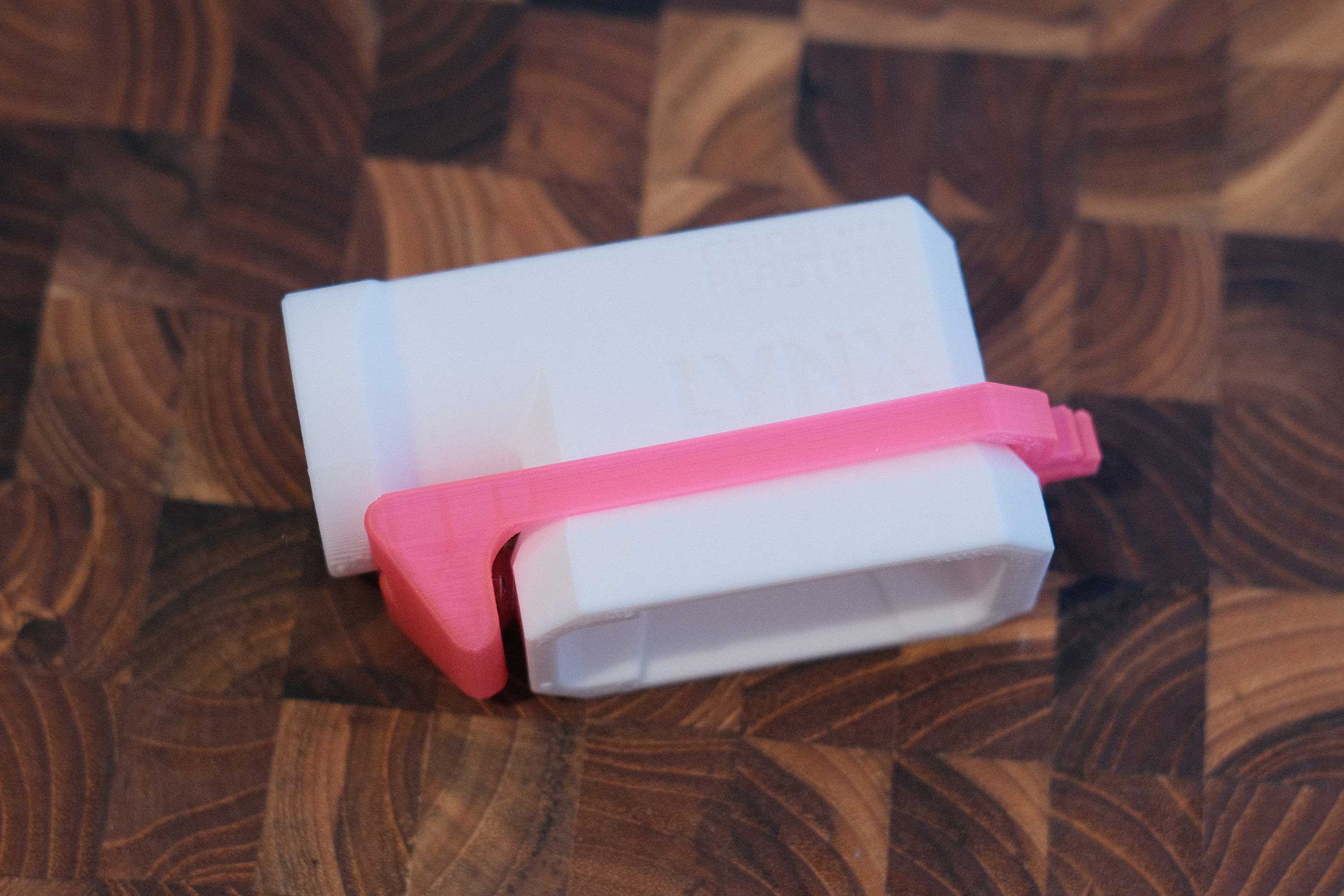 Magwell Assembled
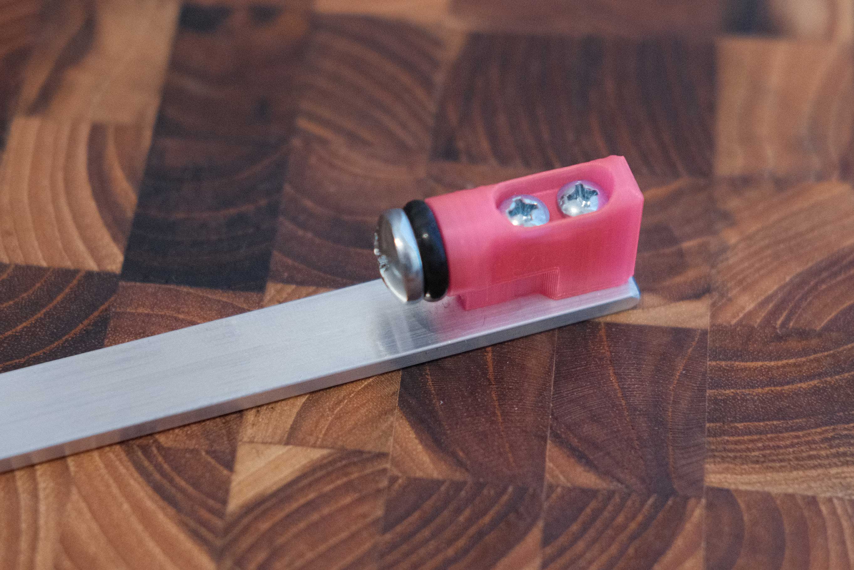
Ram Bar
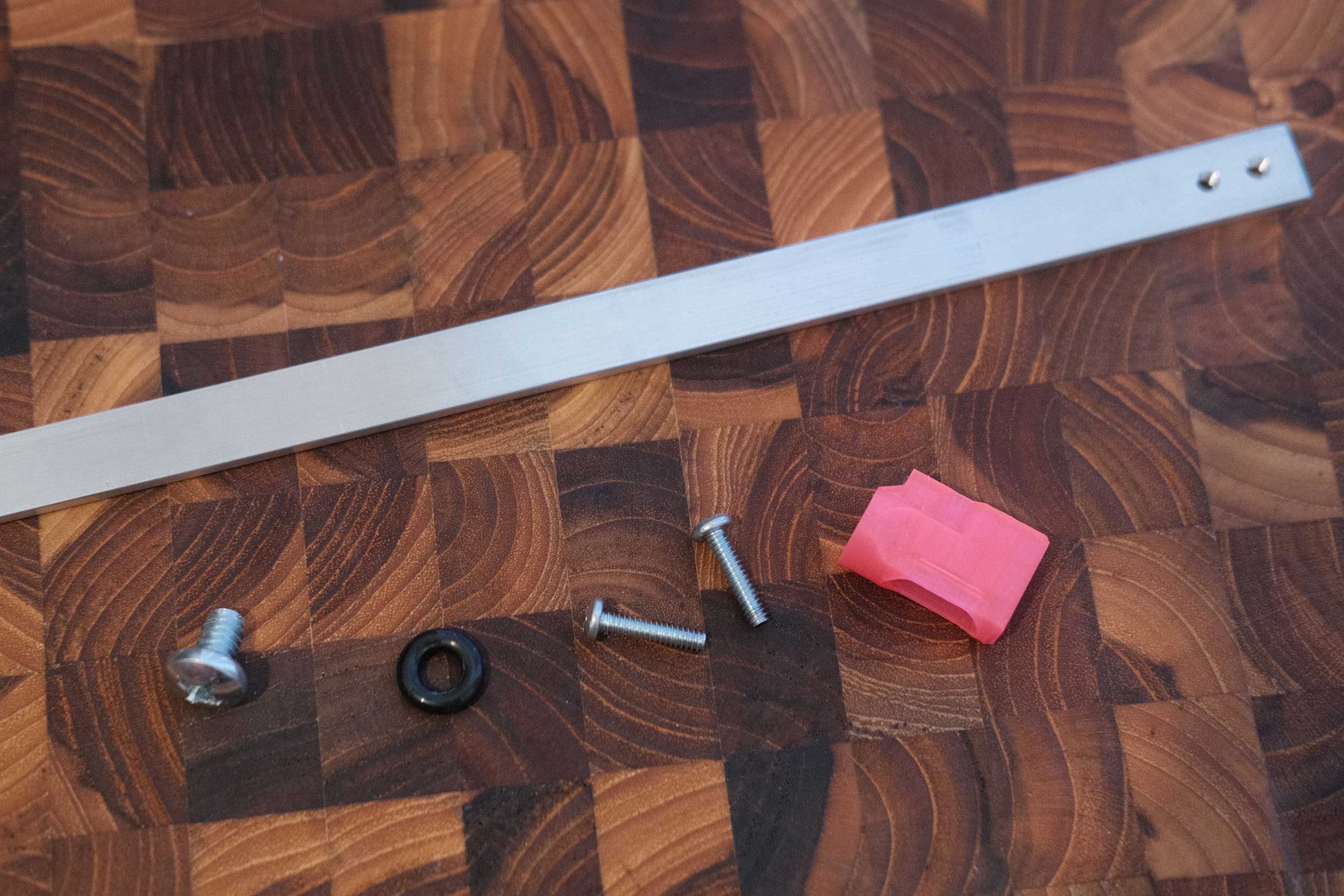
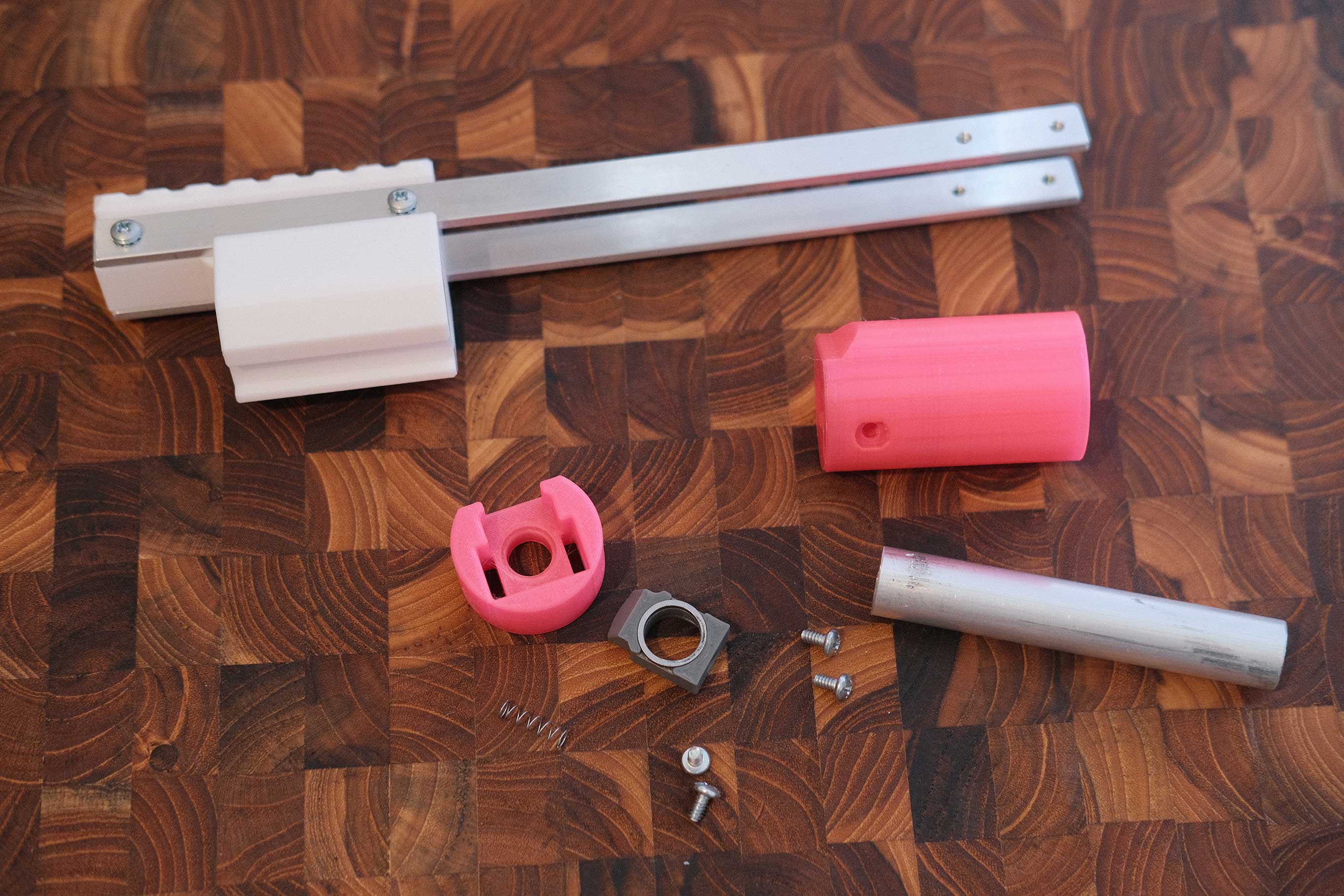
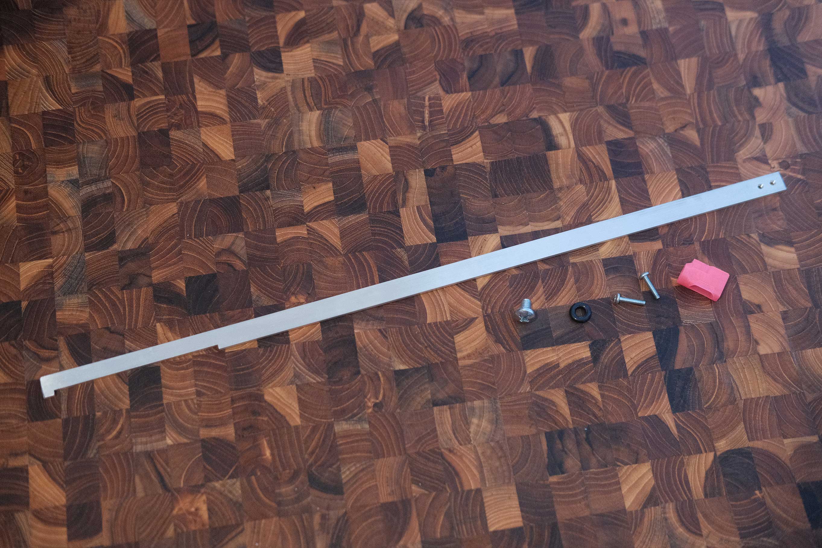 Ram Bar Parts
Take note of the orientation of the bar. The left cutout MUST be on the bottom.
 Ram Bar Parts
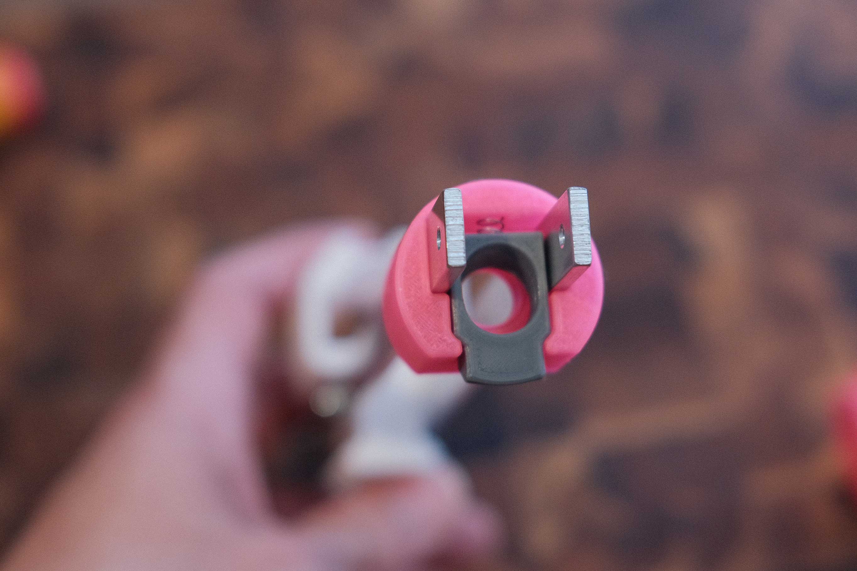
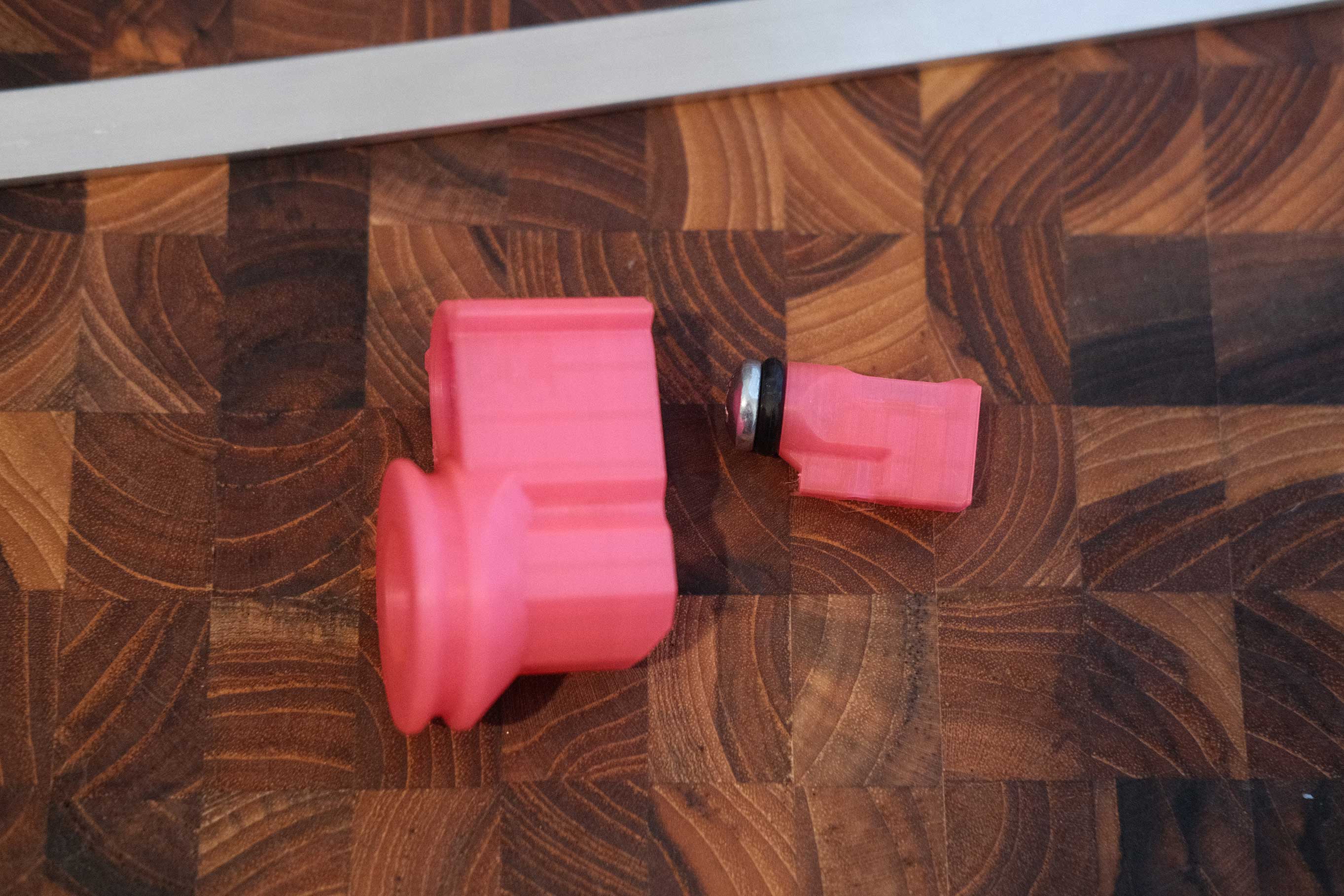 Test Fitment with Turnaround
Similar to the plunger assembly, the ram has an o-ring that is adjusted by tightening the screw.
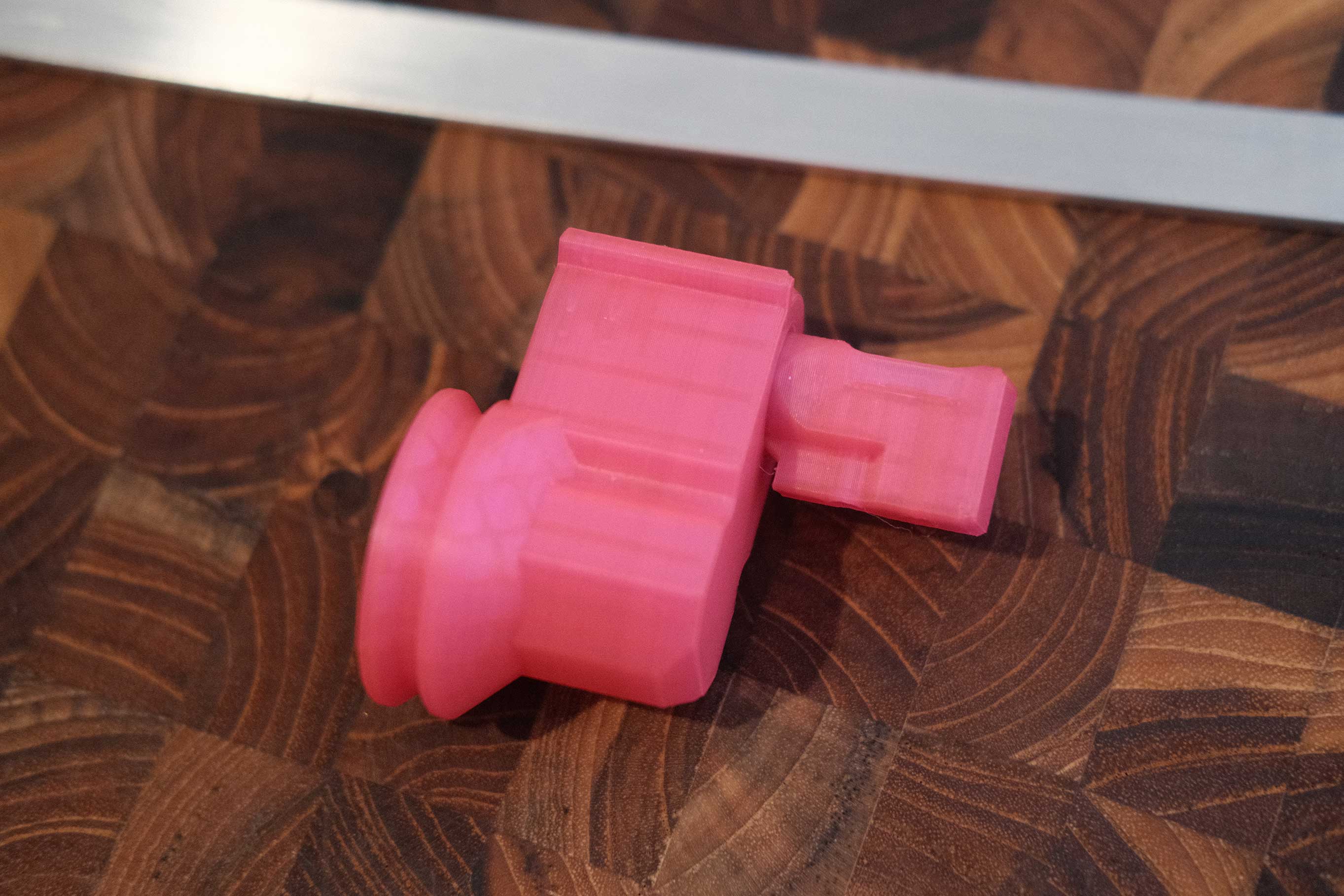 Test Fitment with Turnaround
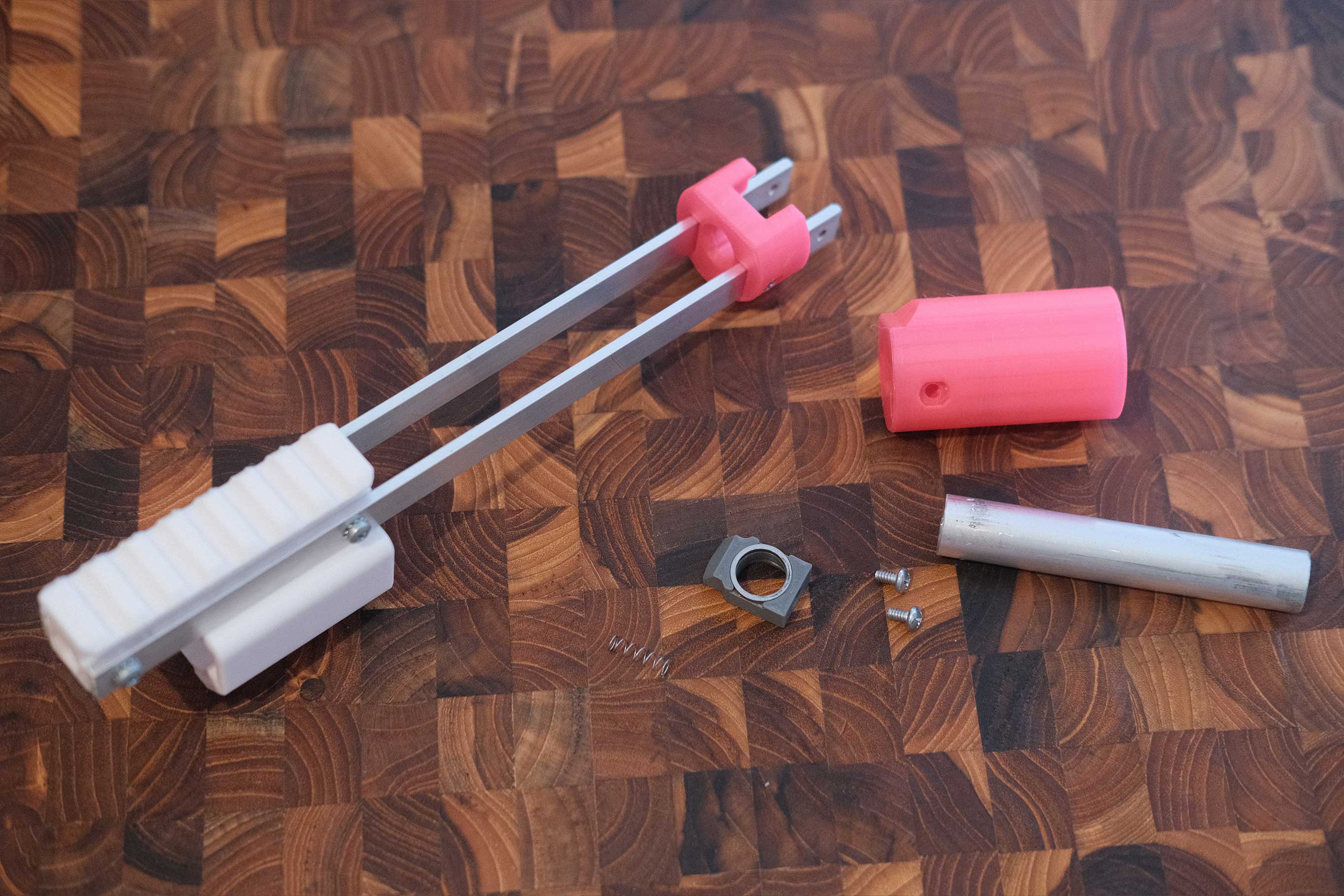
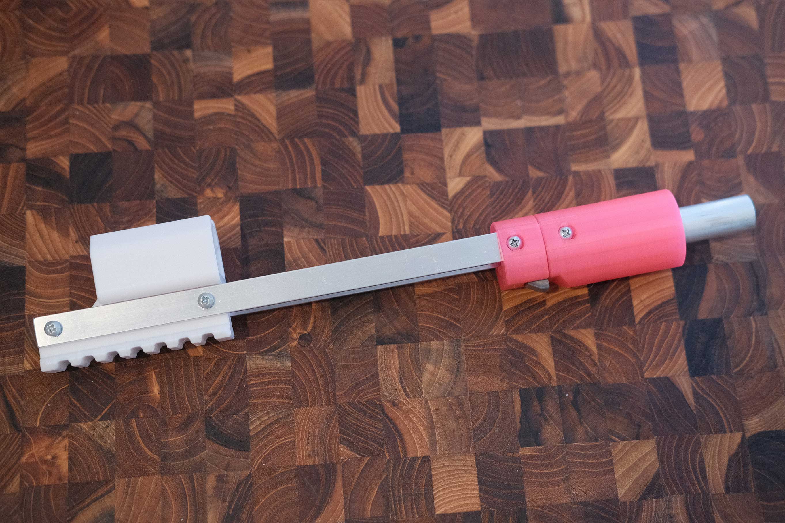
 Ram Bar Assembled
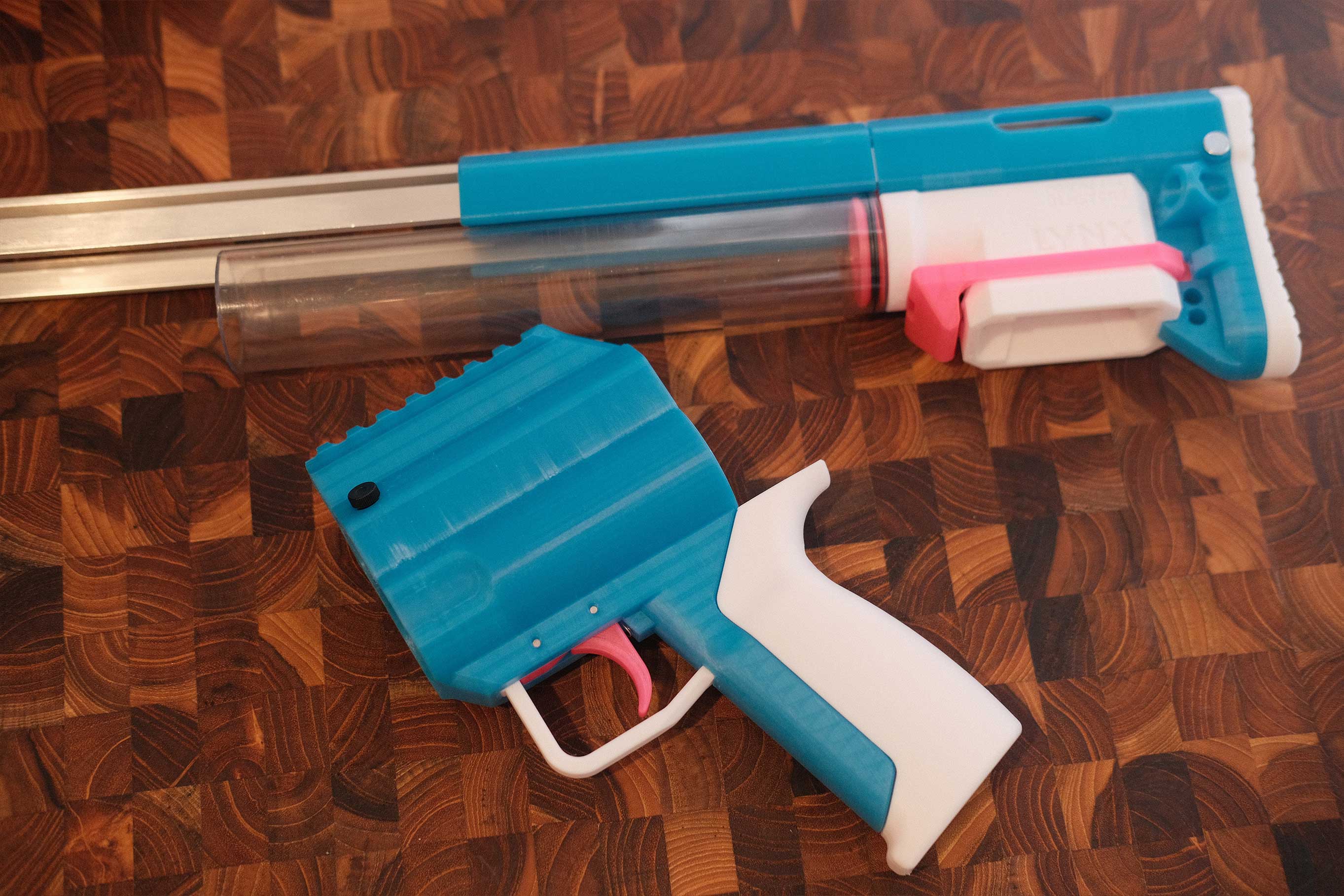
Receiver
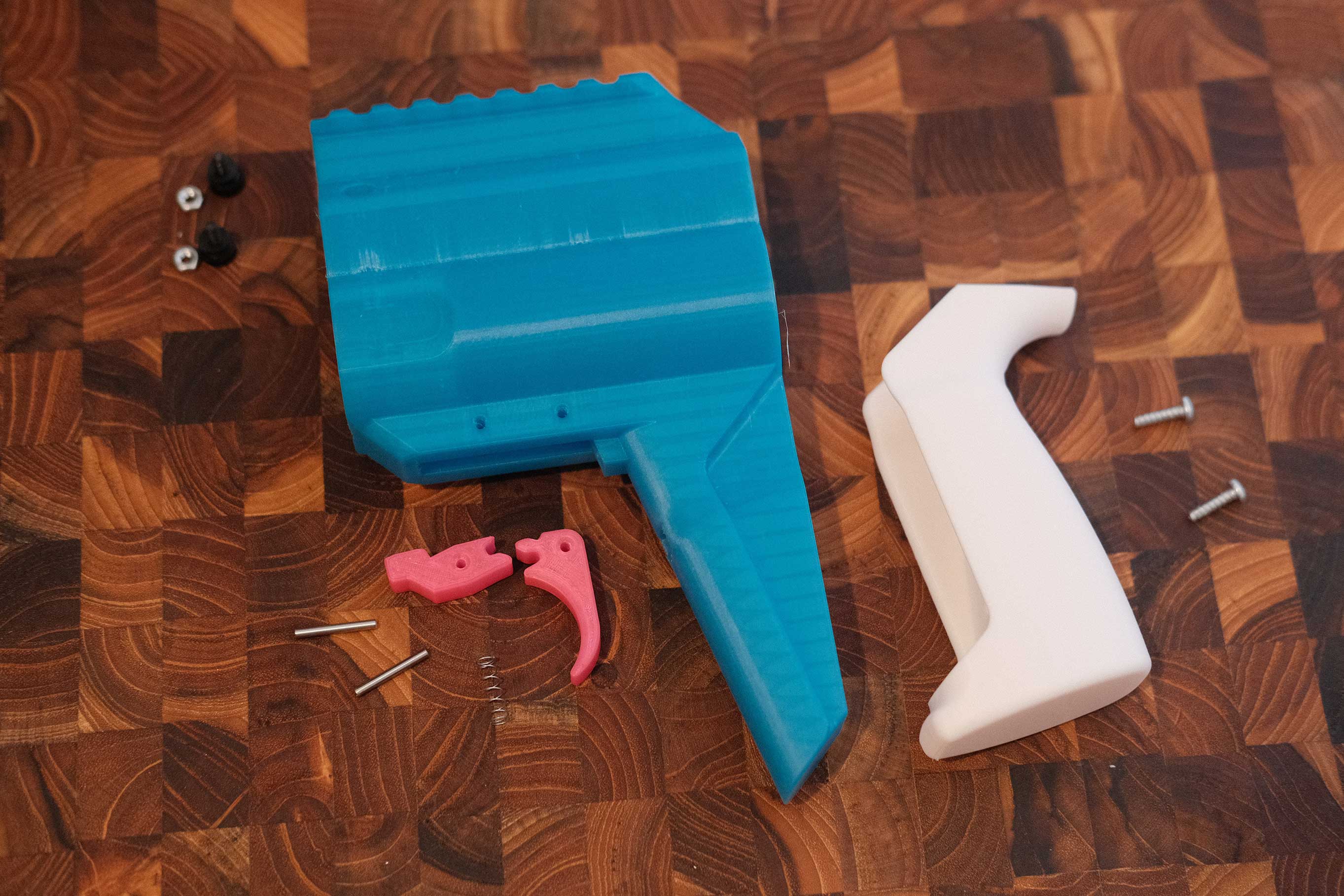 Receiver Parts
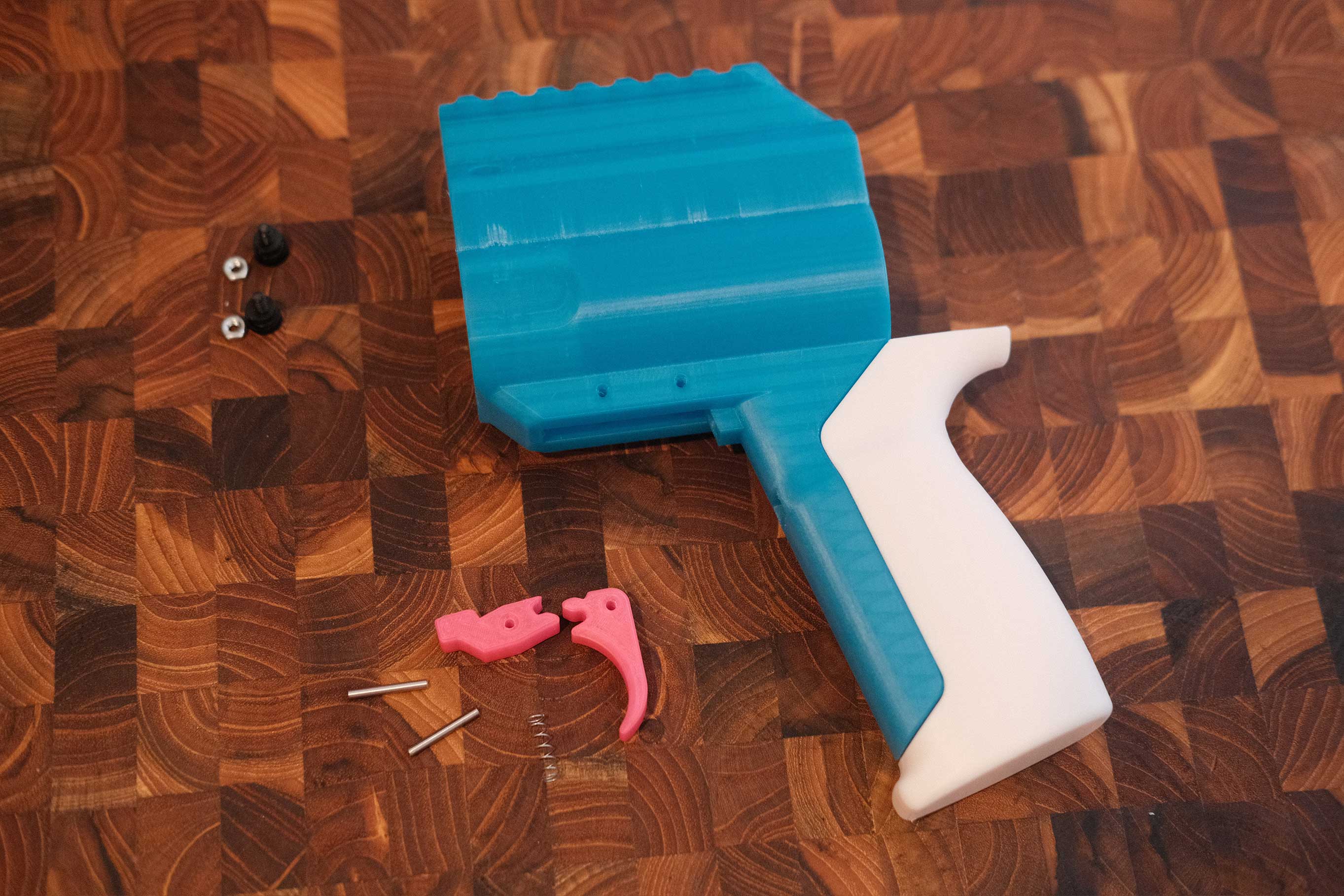 Grip Installed
 Plastic Screws Installed
The plastic screws and matching nuts go on top of the receiver and are responsible for holding the barrel in place. There are hex-shaped recesses inside the receiver to hold the nuts while the screws insert from the outside.
The trigger and sear are pinned in place with shafts. It helps to drill out the holes in plastic with a 3/32 drill bit for clearance.
 Trigger and Sear Installed
Don’t forget the spring!
 Test Trigger and Sear Action
Check the trigger and sear action. When the trigger is not pulled, the sear should be flush.
 Test Trigger and Sear Action
When the trigger is pulled, the sear should rotate up.
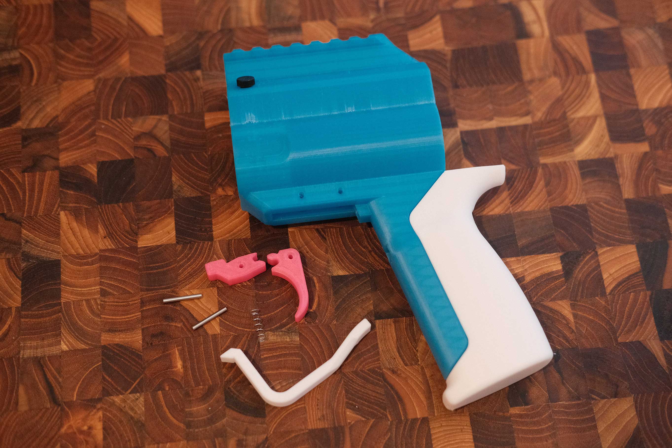
 Receiver Assembled
The trigger guard flex-fits into place.
Pump Catch
 Pump Catch Parts
Oops. Not shown are the 4 screws that secure the catch parts.
 Pump Installed
The 4 screws with toothed washers secure the pump to the front of the bars.
 Smaller Catch Housing
Secure the smaller catch housing first..
 Catch and Spring
…then place the spring and reinforced catch like this. The flatter side of the catch should be facing towards the rear of the blaster.
 Larger Catch Housing
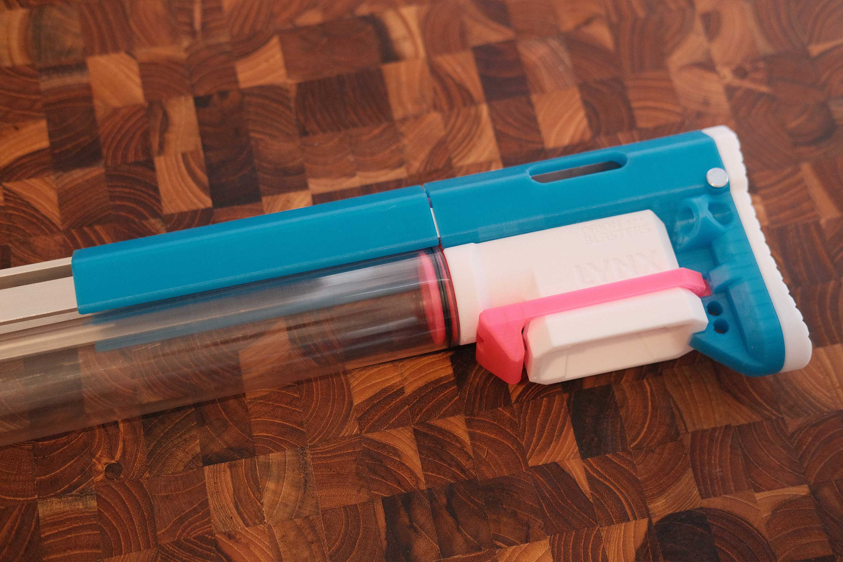
Add the larger catch housing to trap the catch, insert the aluminum tube, and secure the tube with screws.
 Test With Plunger
Test the catch with the plunger assembly.
 Test With Plunger
Inserting the plunger should lock against the catch, and pressing on the catch should release the plunger.
Turnaround
 Turnaround Parts
 Turnaround
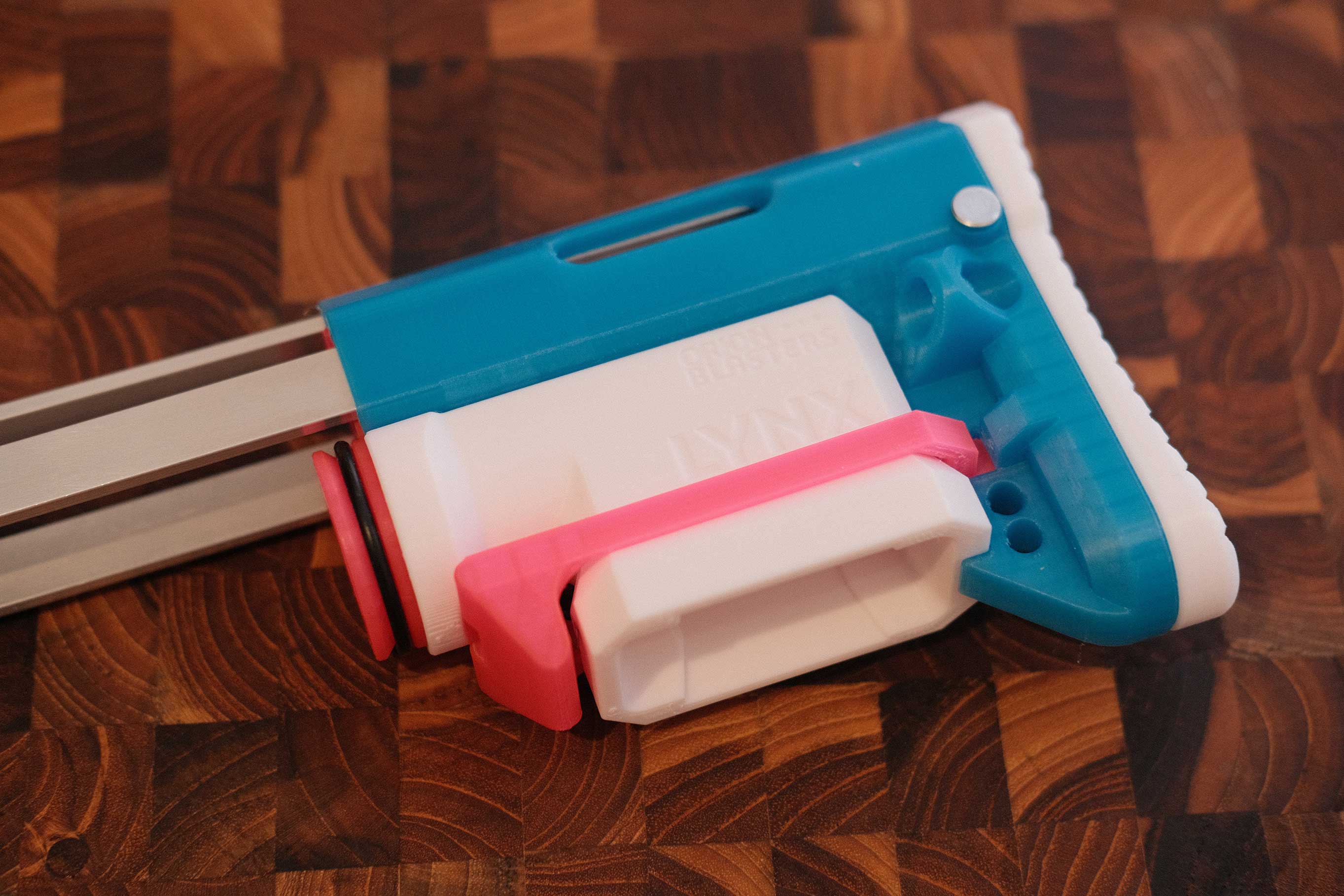
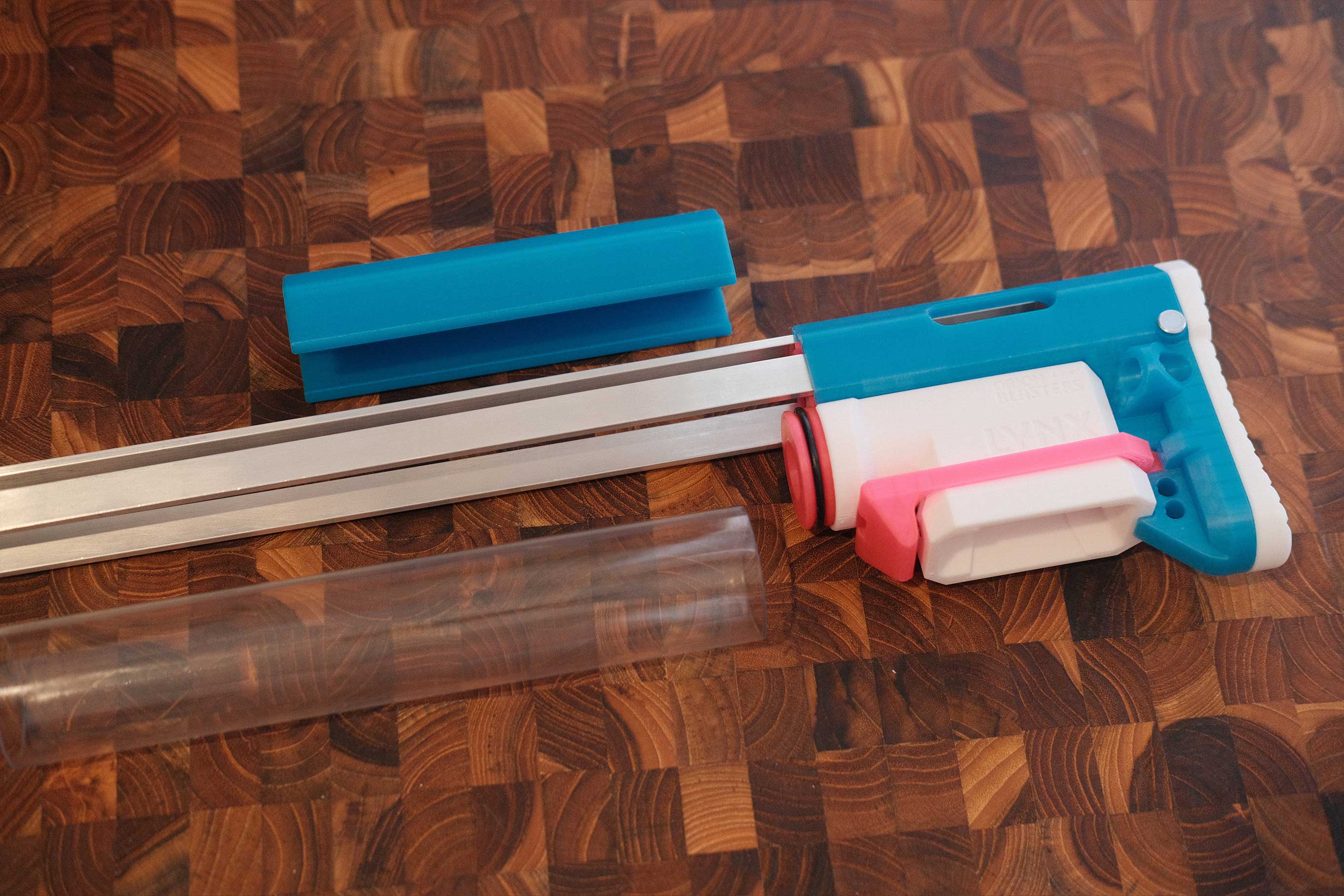
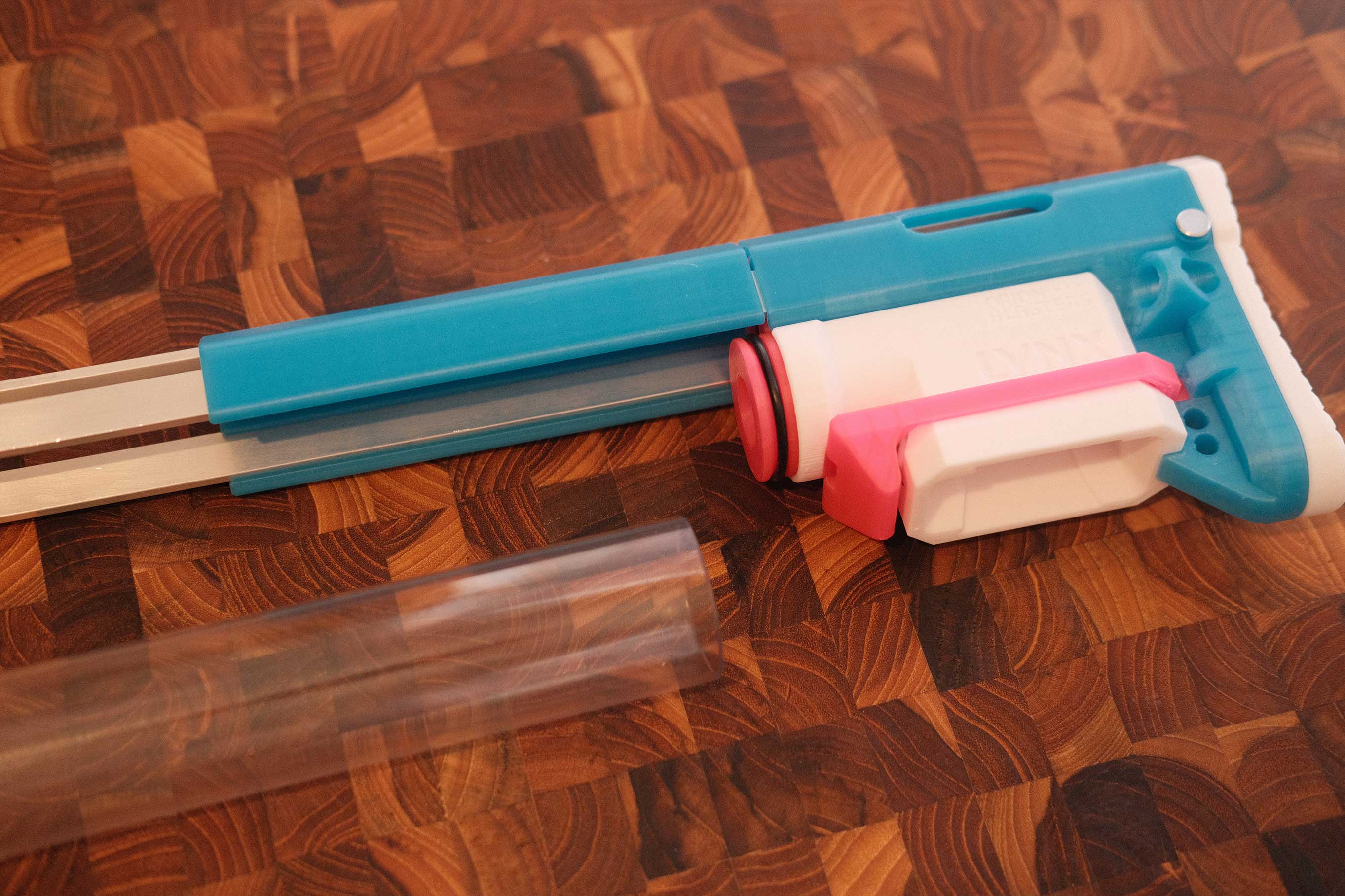
Final Assembly
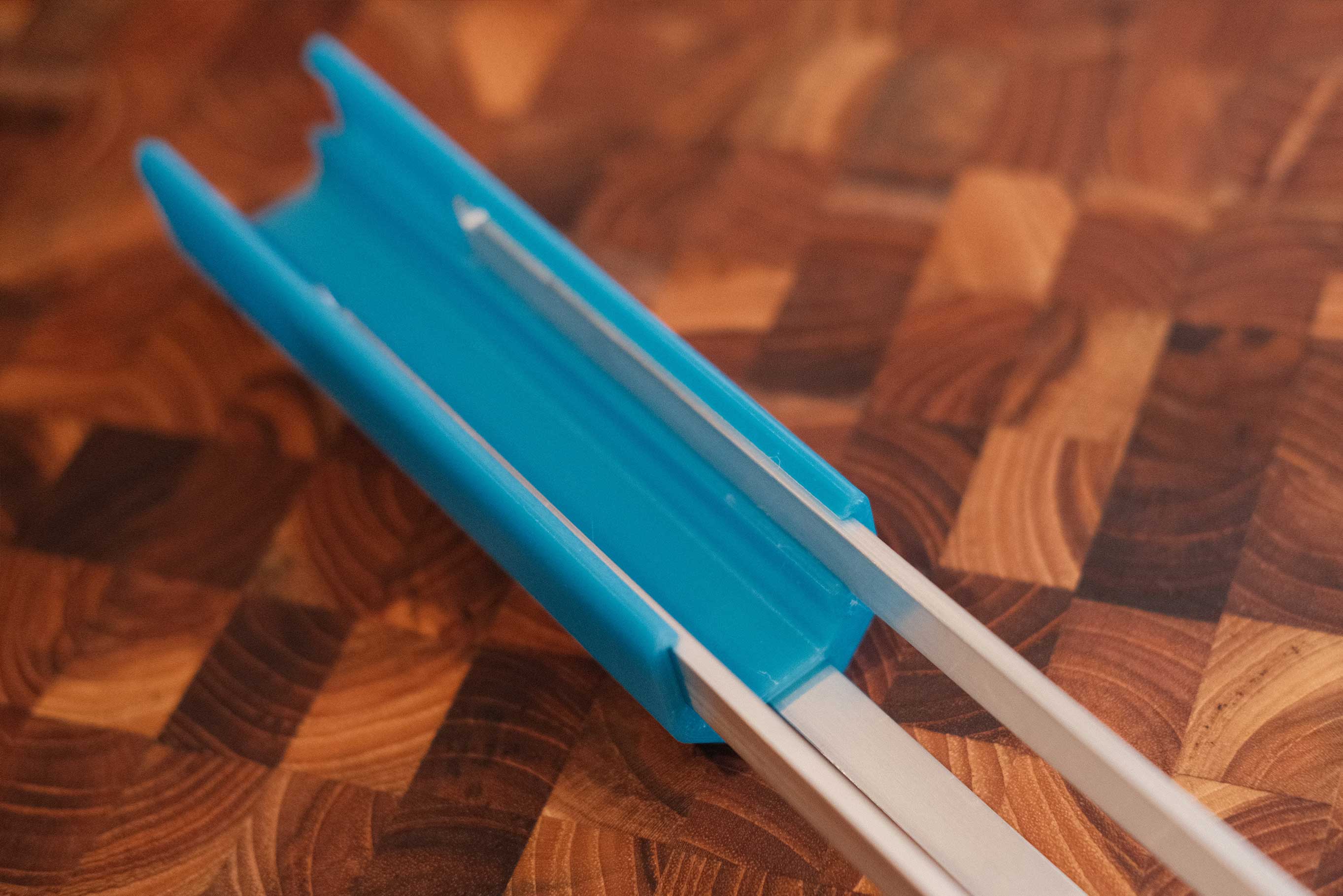
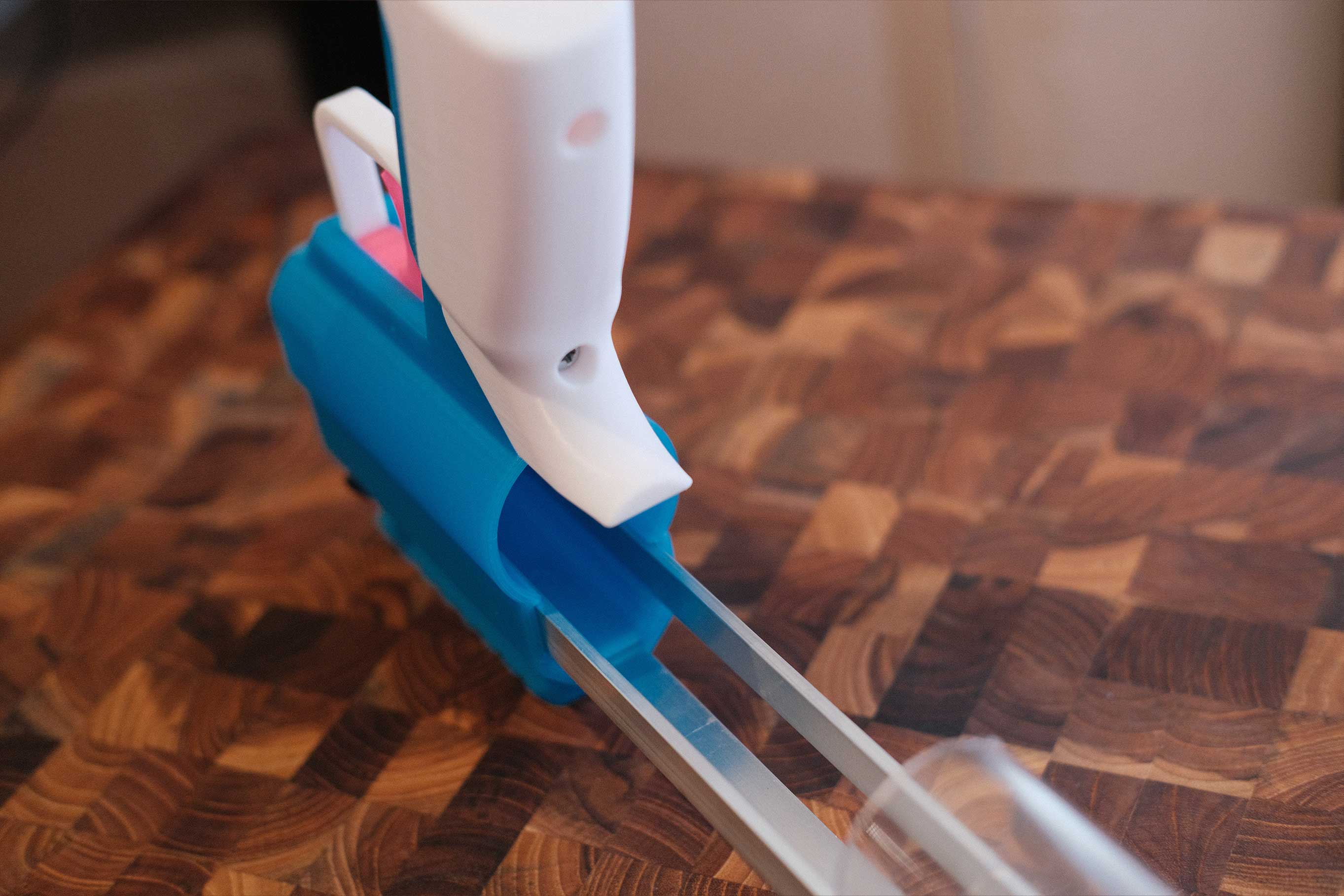
 Stock and Side Bars
 Stock and Side Bars
The bars sit in dedicated side channels, and have notches at the ends to lock in place with takedown pins.
 Add Ram Assembly
Insert the ram assembly.
 Add Ram Assembly
 Add Ram Assembly
It should reach all the way to the back.
 Add Magwell
 Add Magwell
 Add Magwell
The little “ears” align with the 3 bars.
 Add Magwell
Magwell fits like so.
 Add Spacer
 Add Spacer
Slide the spacer on. There are dedicated channels for all 3 bars.
 Add Plunger Tube
 Add Plunger Tube
Twist the clear tube into place around the o-ring.
 Add Receiver
 Add Receiver
Slide on the receiver. There are dedicated channels for all 3 bars.
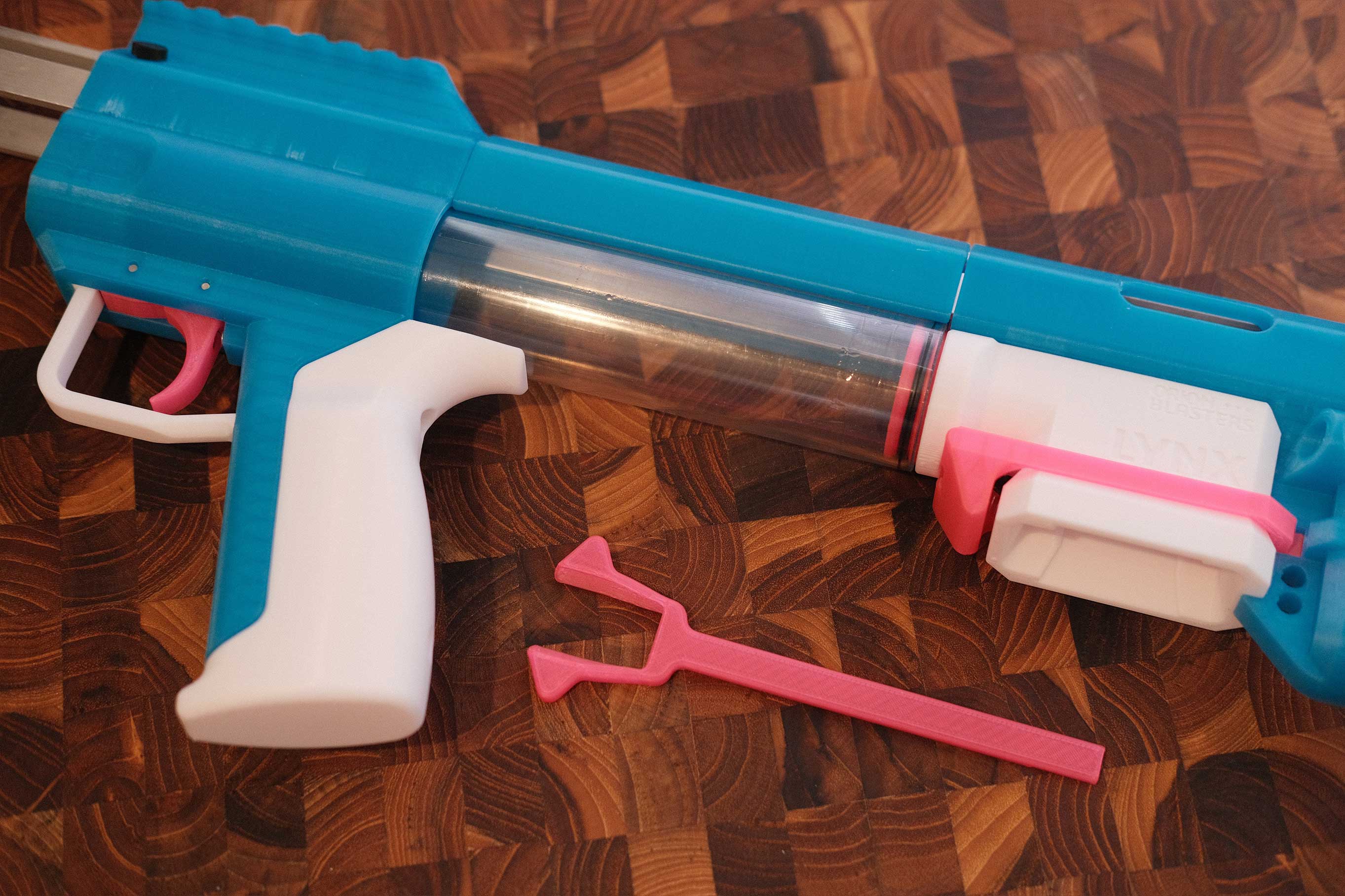 Add Thumb Release
If you are using the optional thumb release, add it before sliding the receiver all the way.
 Add Thumb Release
 Add Plunger and Spring
Add some silicone grease around the oring to facilitate plunger action against the clear tube.
 Add Plunger and Spring
 Add Ram Bar
 Add Ram Bar
You will need lift up the ram bar to slide the pump assembly through. The pump fits in the notch in the ram bar.
 Add Picatinny Rails
 Add Picatinny Rails
 Add Picatinny Rails
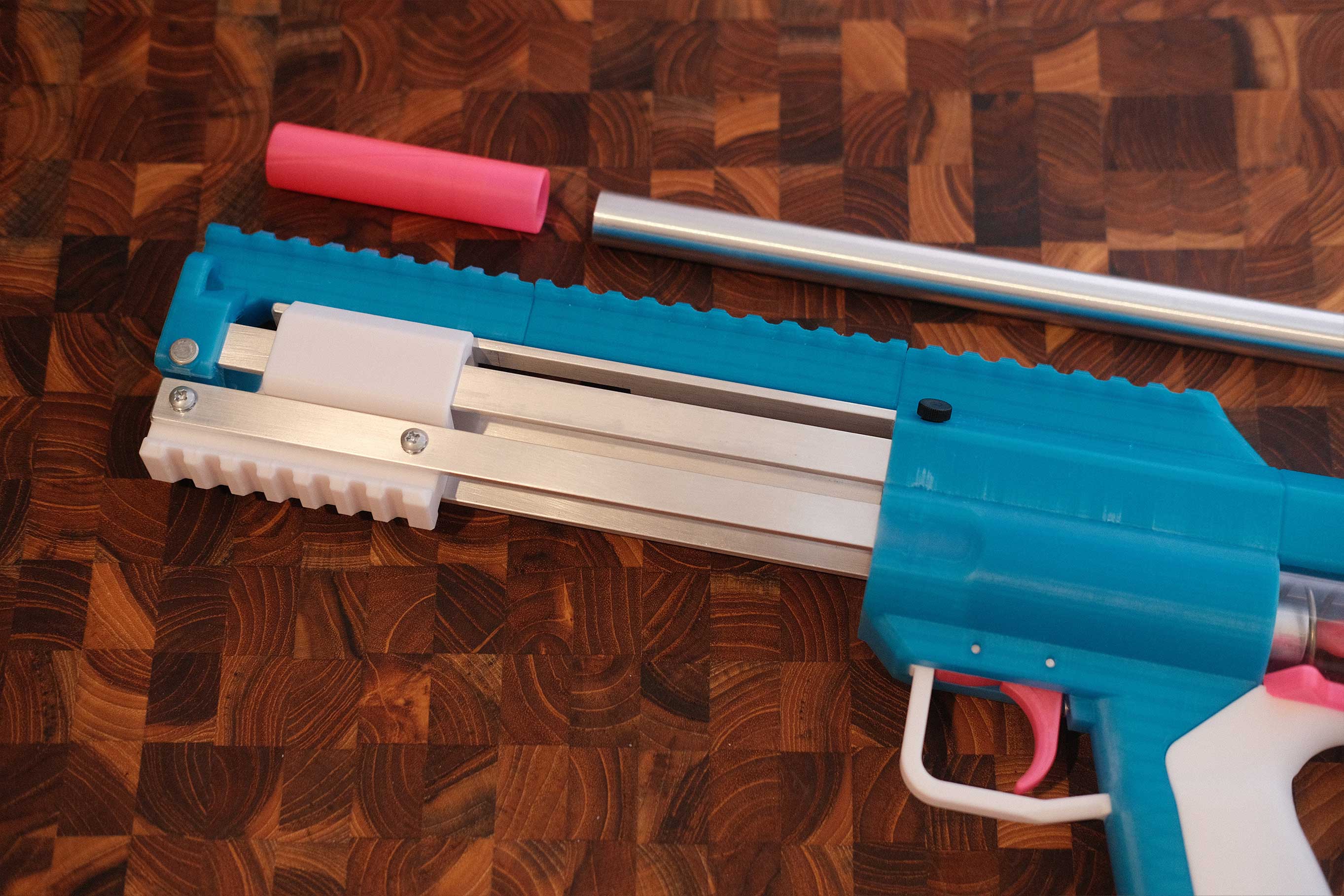 Add Barrel
 Add Barrel
You might need to loosen the top plastic screws to feed the barrel through. As the barrel bottoms out, it will push through the two o-rings inside the turnaround. Be careful that you don’t push them out of place. Retighten the top plastic screws to secure the barrel.
Complete
Your Lynx is complete!