Build Log
Table of contents
- Sorting the Fasteners
- Prepping the Rails
- Z Rail Assemblies
- Assembling the Frame
- Z Joints
- Deck
- Z Drive
- Z Idlers
- Z Endstop
- Bed
- ZeroFilter
- Y Axis
- X Axis
- A/B Idlers
- A/B Drives
- X/Y Joint Assemblies
- Y Endstop
- Gantry - Mounting A/B Idlers
- Mounting A/B Drives
- Klicky
- Rear Gantry
- Mounting X Axis
- X/Y Belts
- Mini Afterburner
- Gantry Install
- Z Belts
- X/Y Belts (Revisited)
- All Belts Done
- Mini Afterburner (Revisited)
- Front Skirt
- Electronics
- Wiring
- Mini Afterburner (Revisited)
- Umbilical/Cable Chain
- Wiring
- Initial Build Complete
- Neopixel Front Button
- Panels
- Comparison to 300mm Trident
- Neopixel Sticks for Chamber Lighting
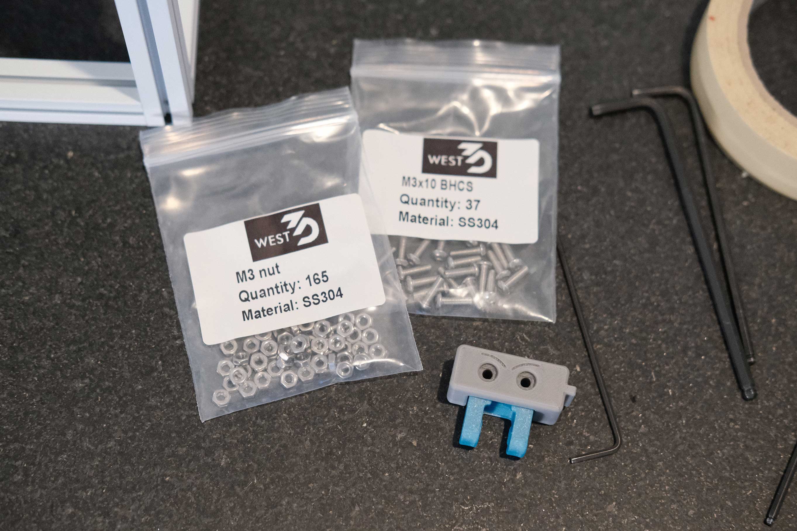
Sorting the Fasteners
 Fasteners Organized
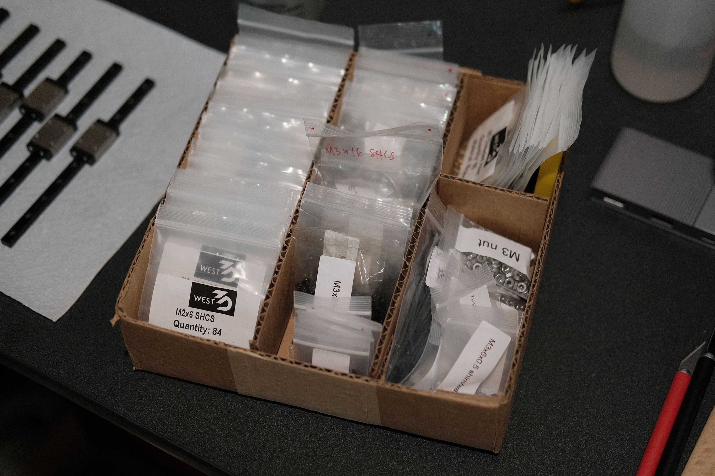
The DFH Micron kit comes with all the required fasteners, but in a mix of black oxide and stainless steel, and a mix of resealable zip pouches and tear pouches. With the colors I chose (Fusion Filaments’ Electrolytic Deuterium and Mushroom Cloud Grey), I wanted the lighter color of stainless steel so I bought a set of West3D’s “Best Damn Fasteners” for the Micron. They really are great!
Organize the screws. Left column contains West3D’s “Best Damn Fasteners”, sorted from smallest to largest. Middle column contains the stock fasteners from DFH’s kit. Right columns hold nuts, shims/washers, heatset inserts, etc.
Prepping the Rails
 Prepping Rails - 1
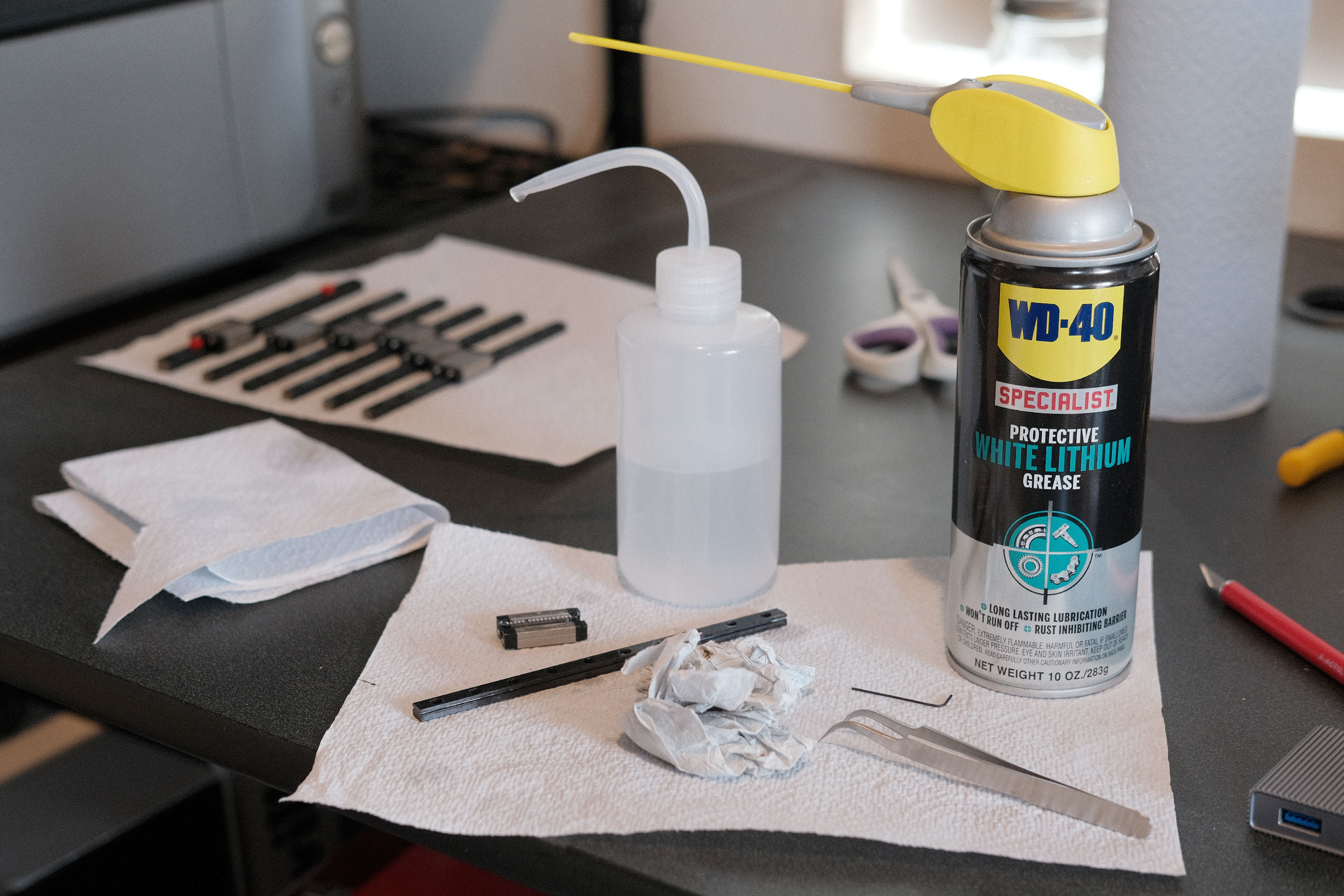
Flush the rails and carriages with some isopropyl alcohol and use the itty bitty allen key to push a bit of paper towel through the rails’ grooves. Spray a bit of white lithium grease into the carriages’ ball bearings until they are all coated, but not sopping wet. Add a bit of white lithium grease to the rails’ grooves, and spread and coat the rail to prevent rust.
 Prepping Rails - 2
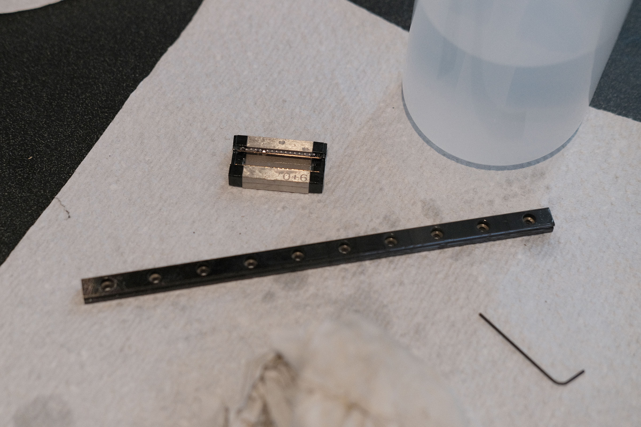
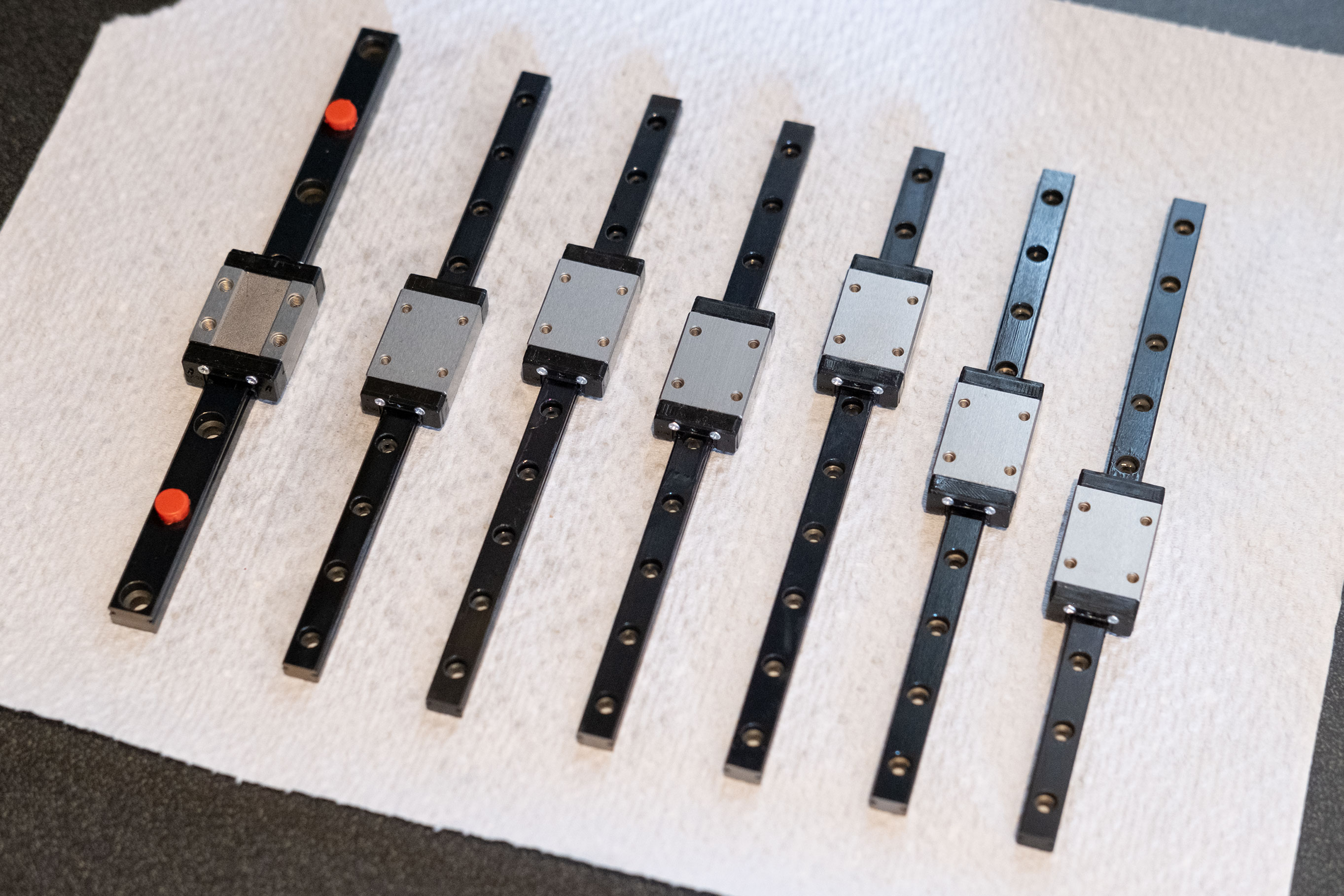
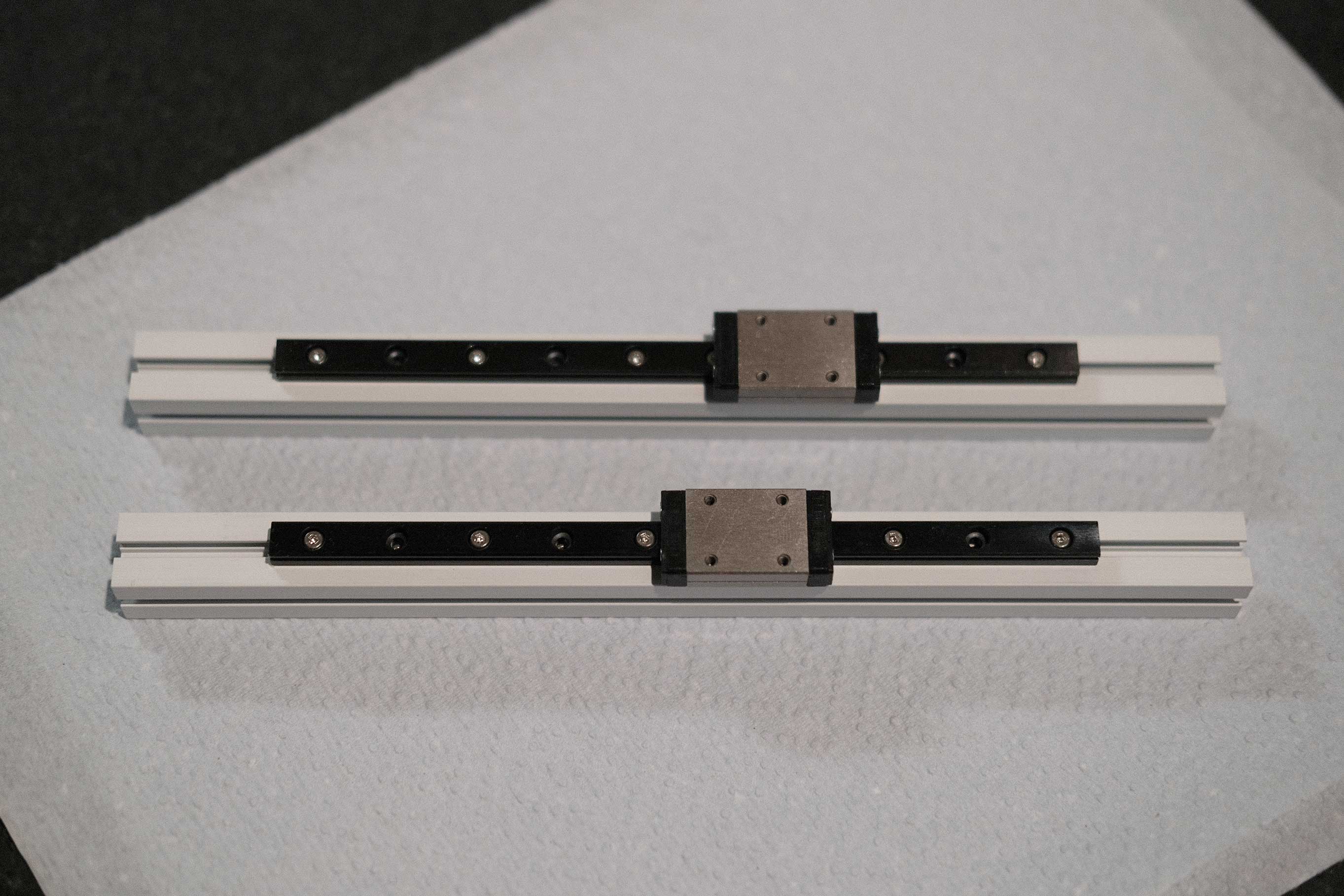
Re-assemble the carriages and rails, move the carriages back and forth along the entire lengths to ensure good spread of the white lithium.
 Prepping Rails - 3
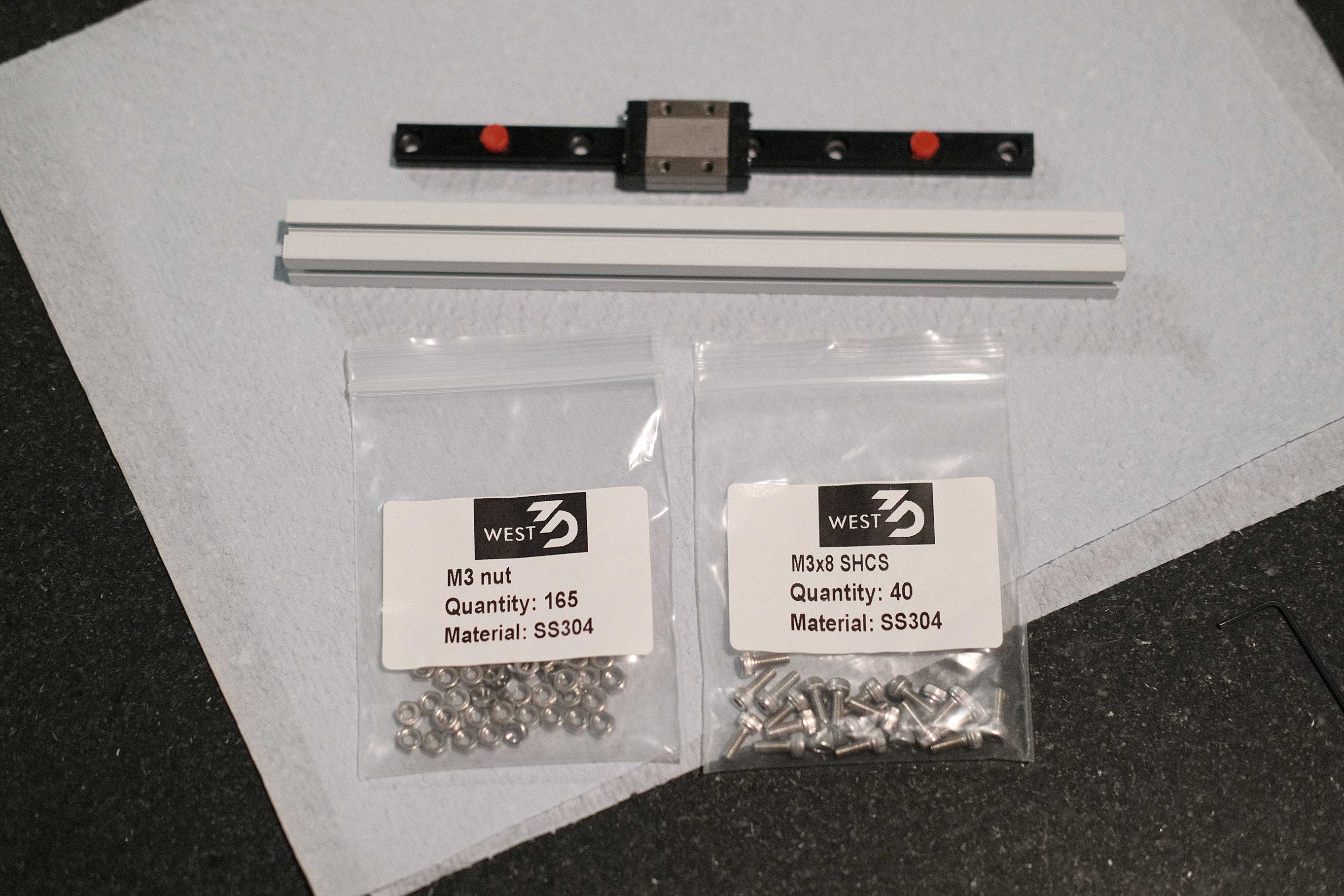
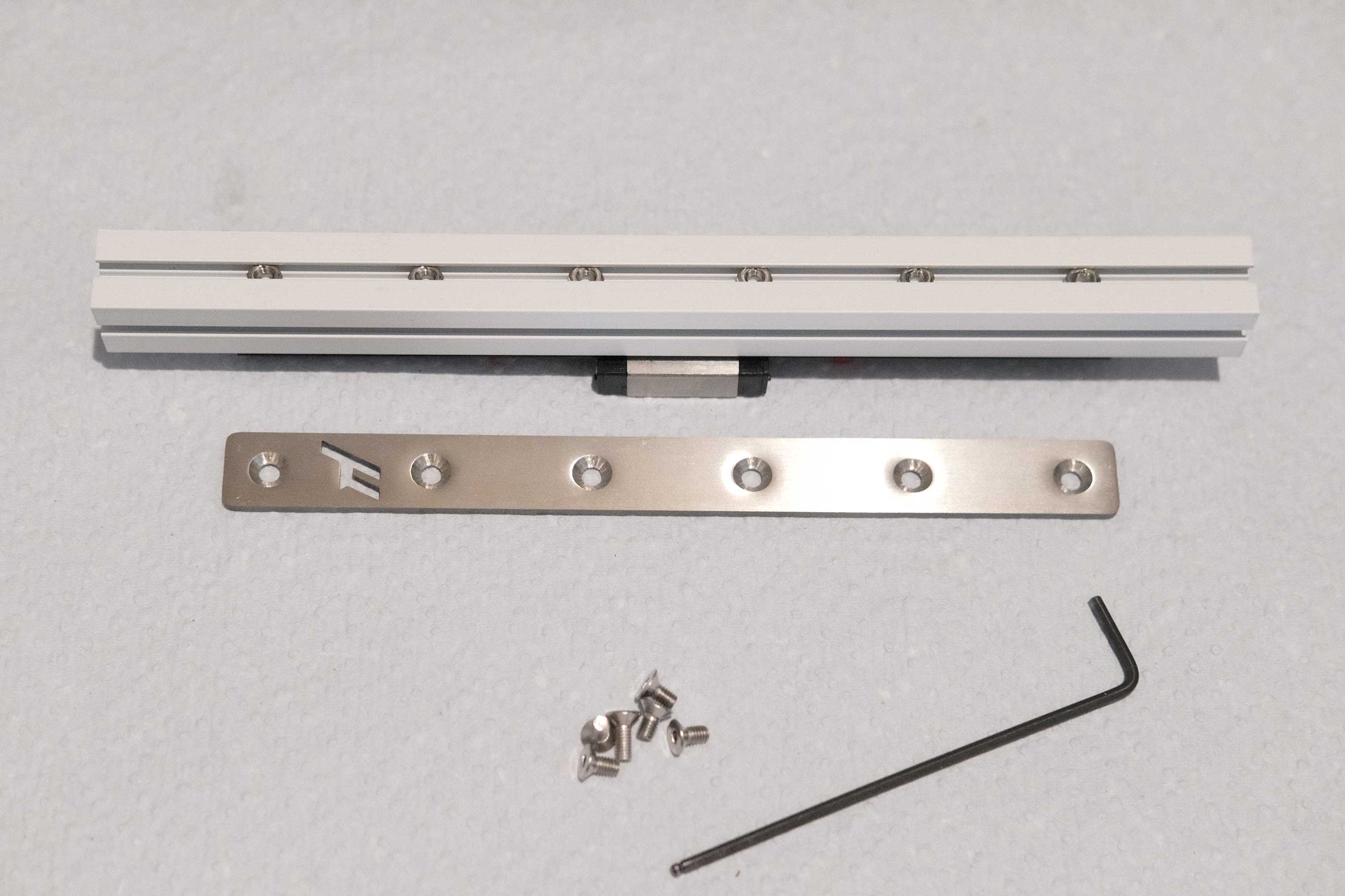
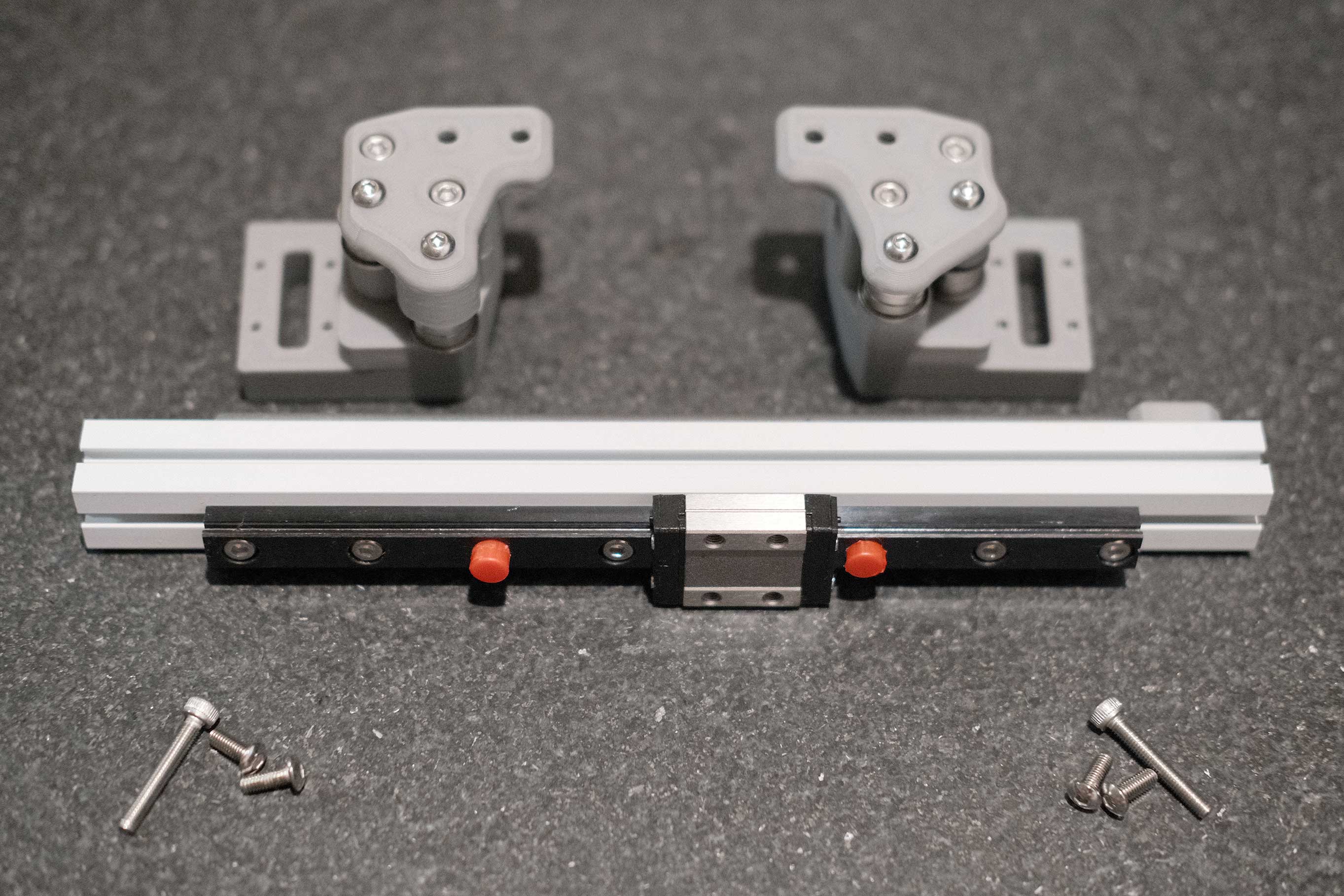
Z Rail Assemblies
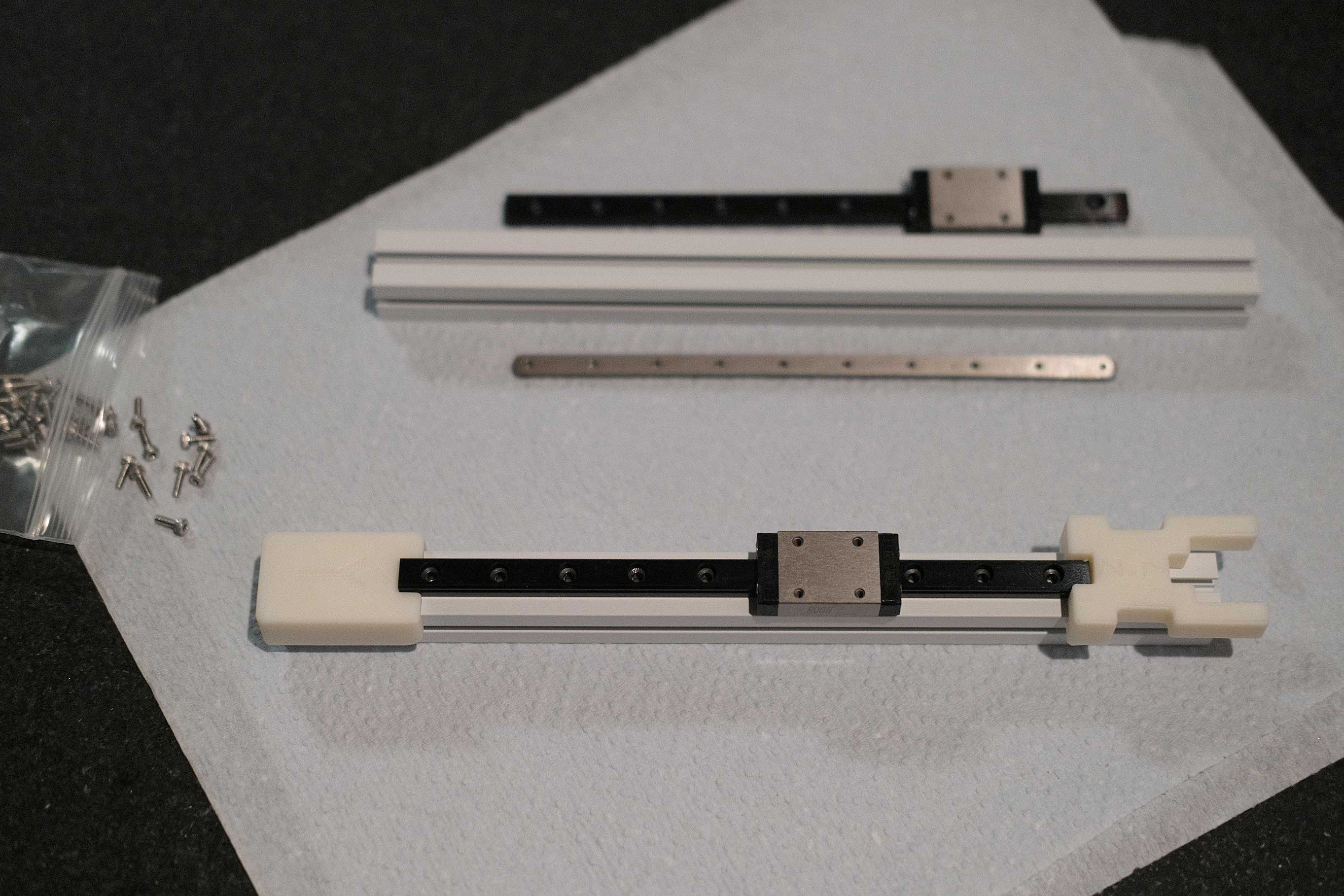
Slide a nut bar into the aluminum slot. Use a small allen key to push as necessary.
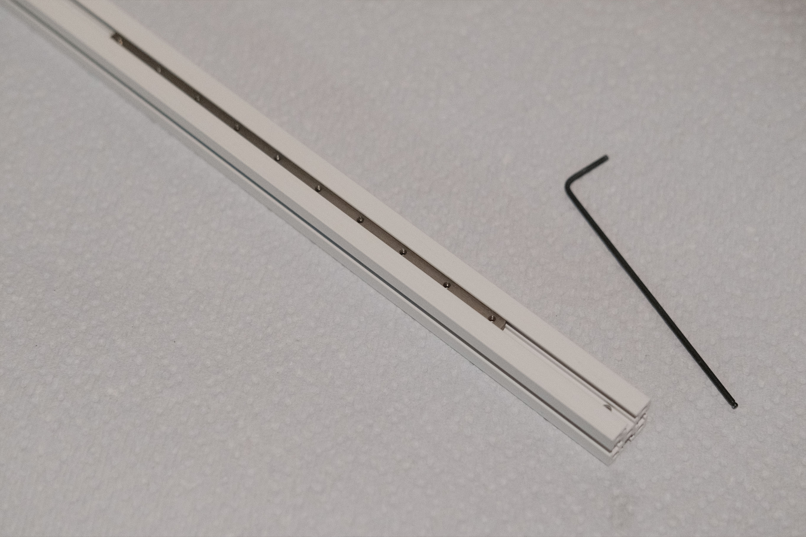 Insert Nut Bar into Extrusion
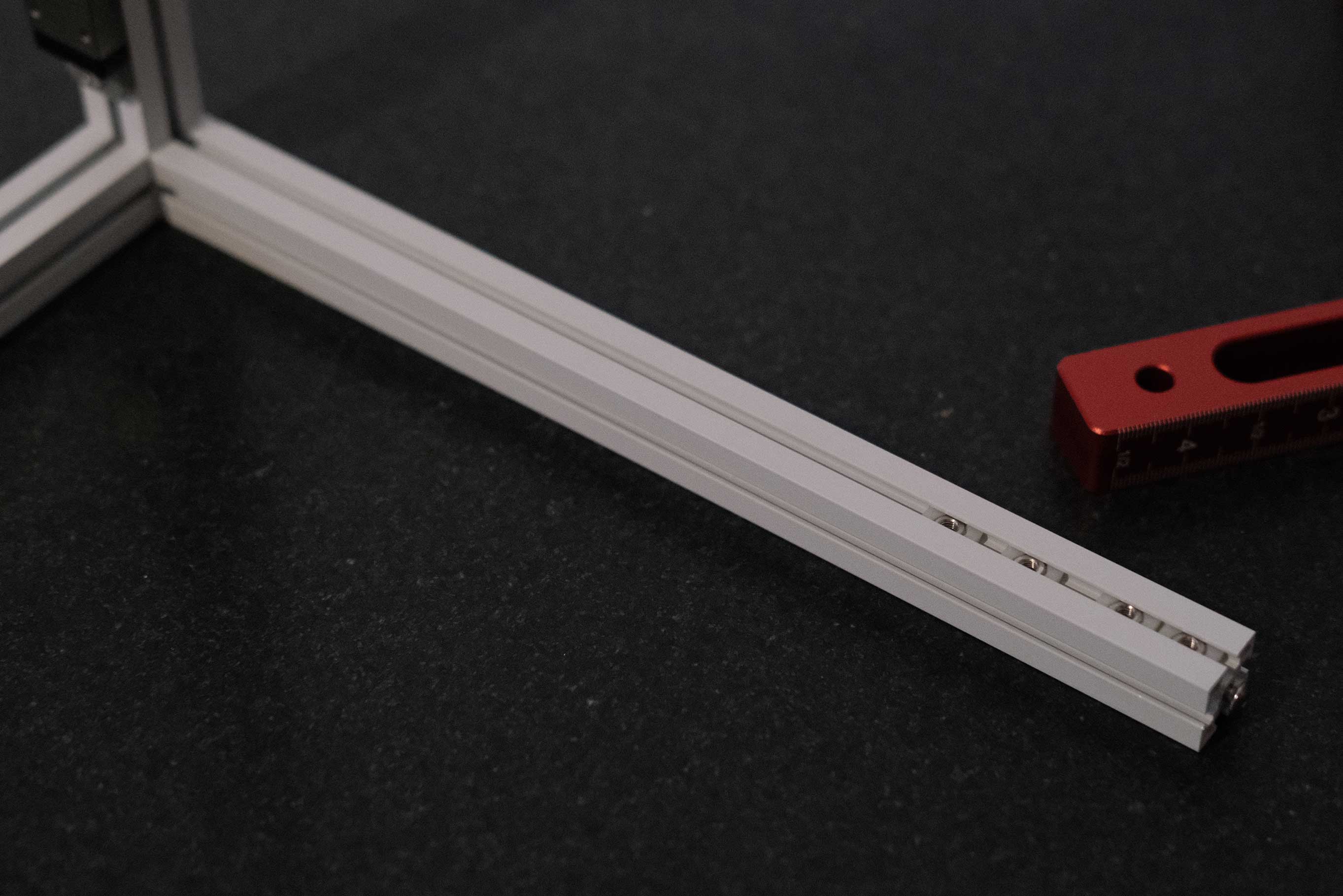
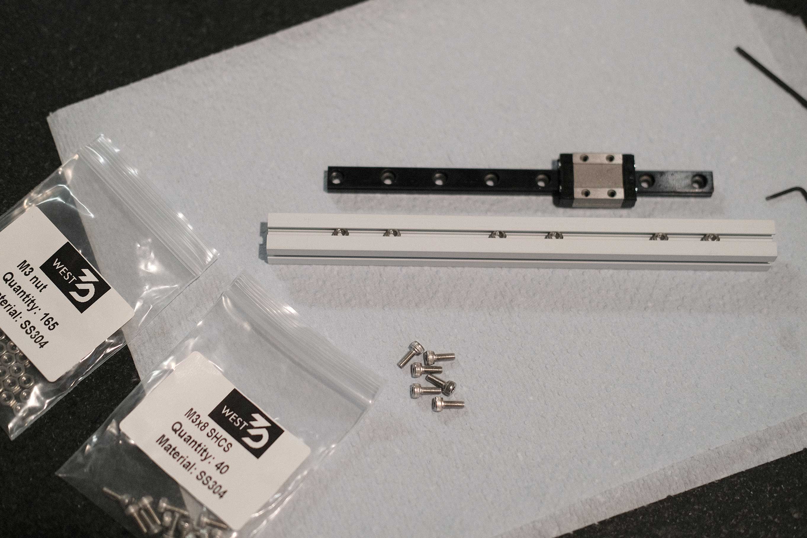
Align the MGN7 linear rails so that the holes line up to the nut bar. Add two M2x6 SHCS to the ends and lightly screw them in.
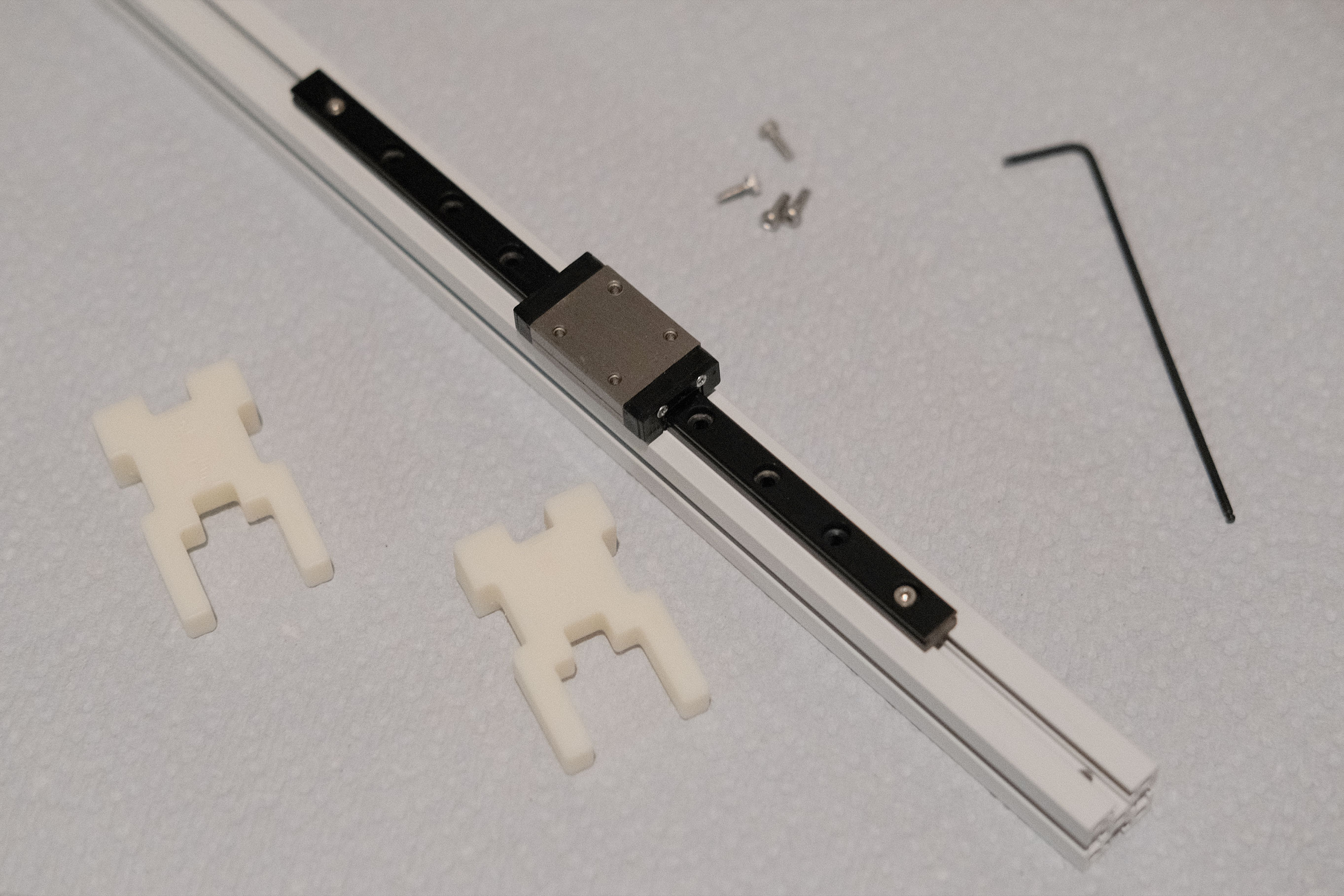 Place the MGN7 Linear Rail
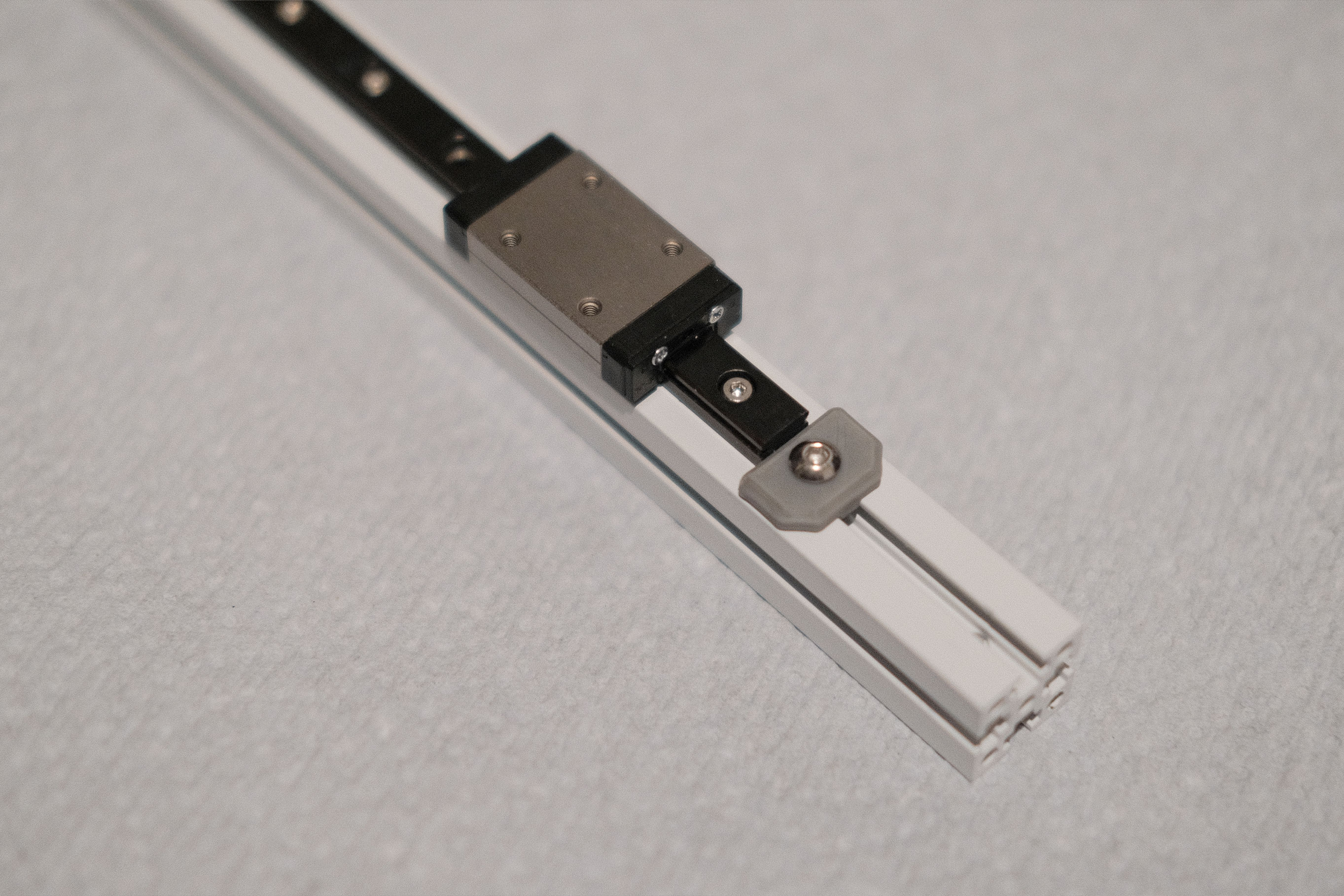
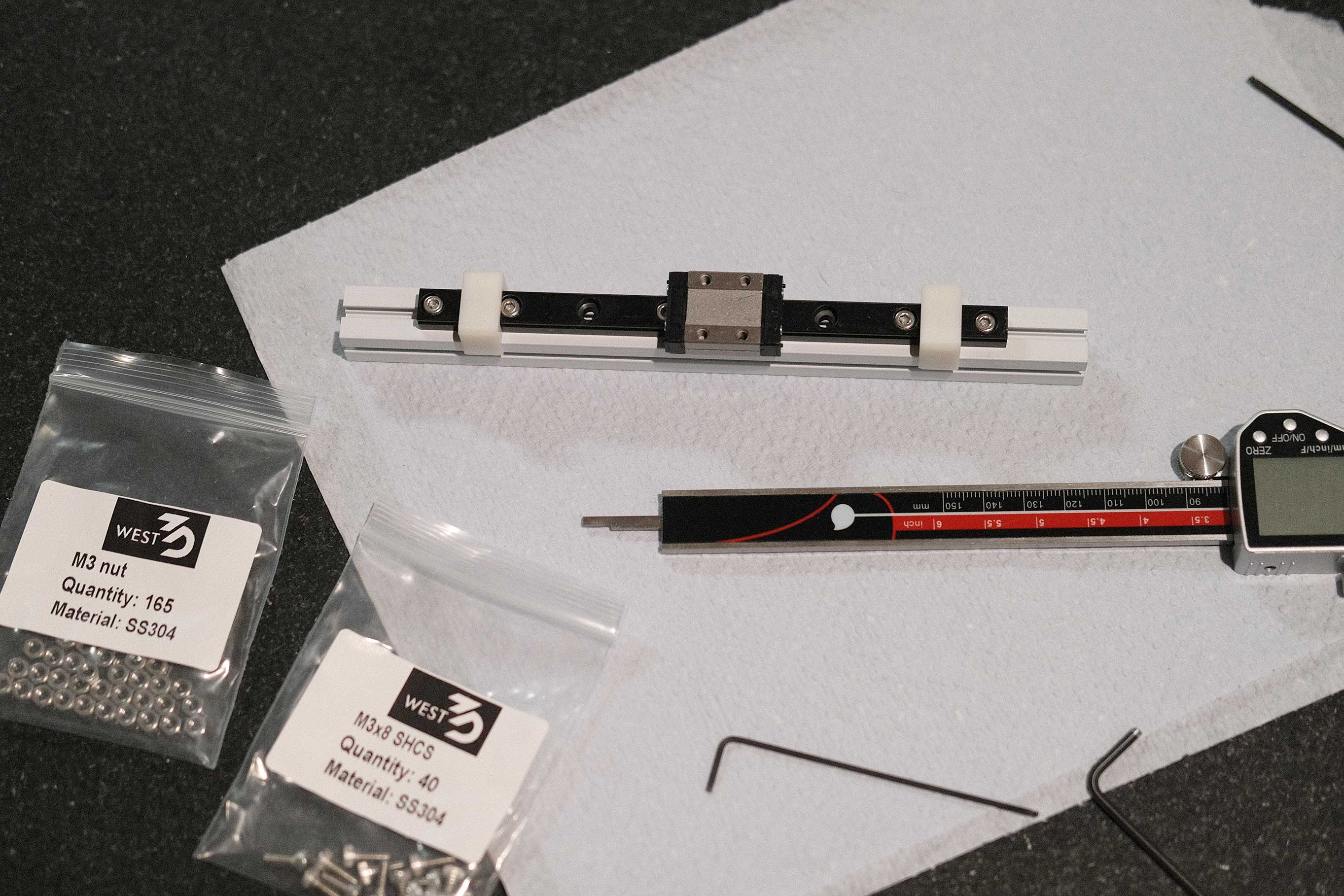
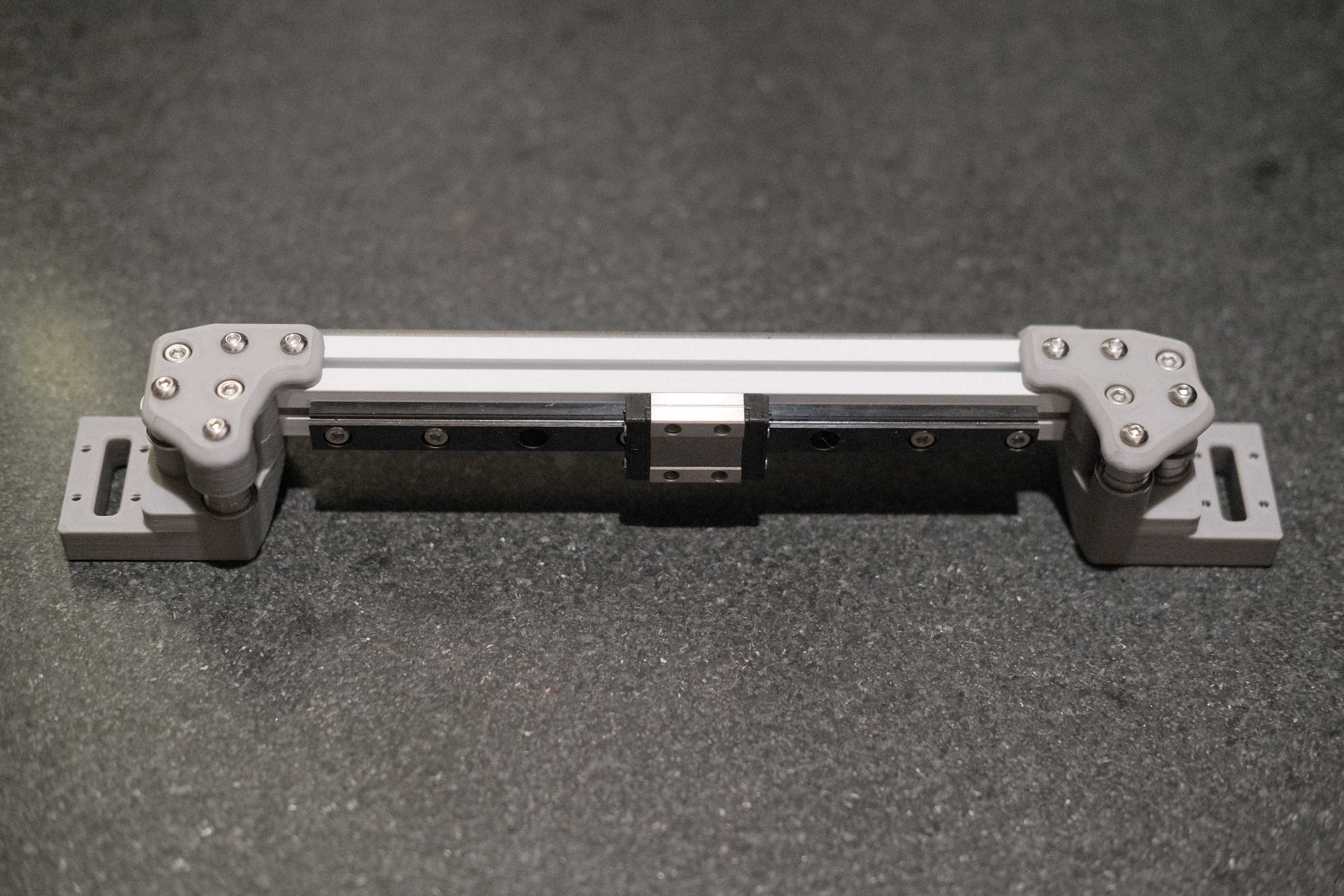
Attach the printed jigs to both ends of the linear rail and ensure they are flat against a surface. This will center the rail and set it ~36mm from the end of the aluminum extrusion.
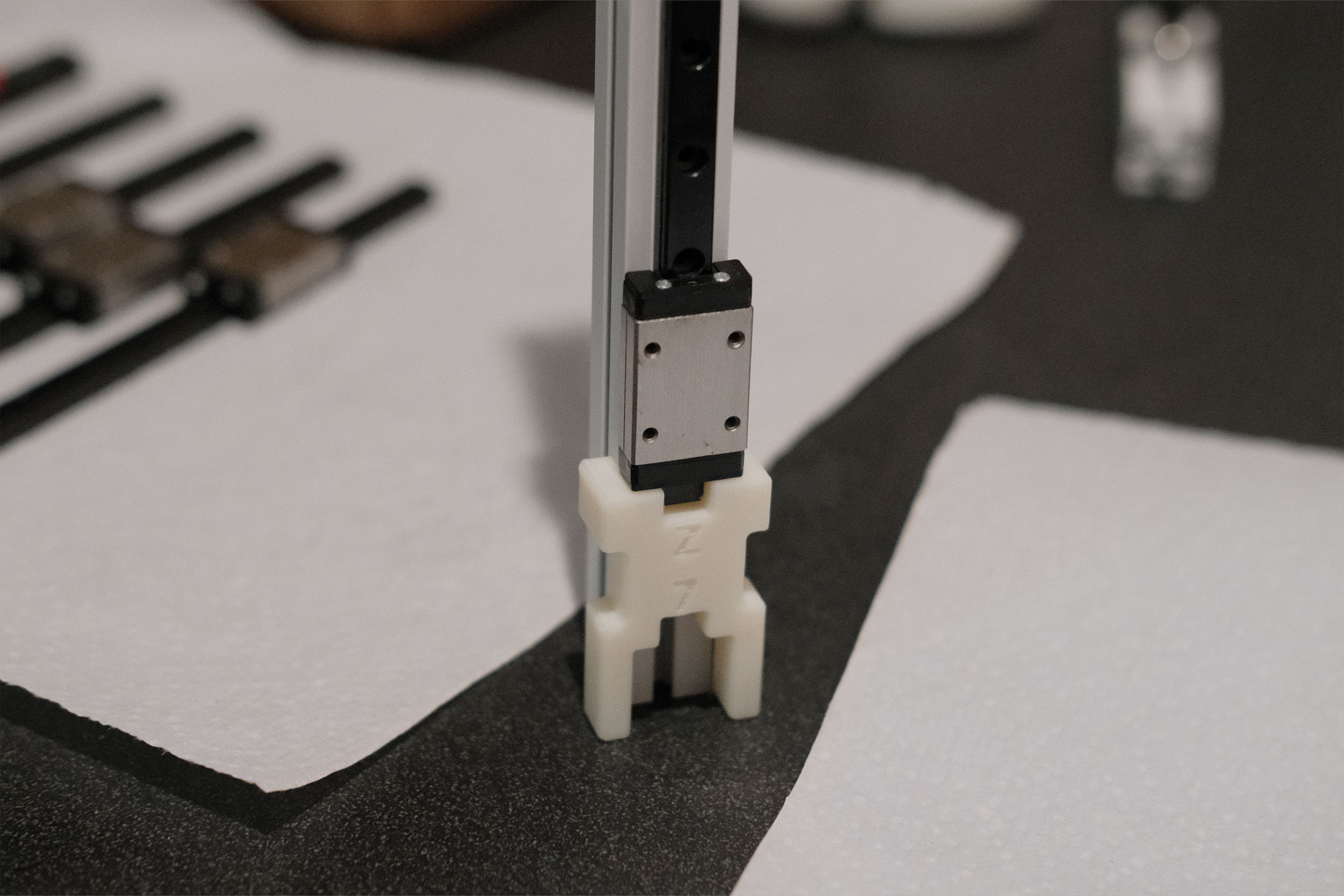 Printed Jig for Spacing
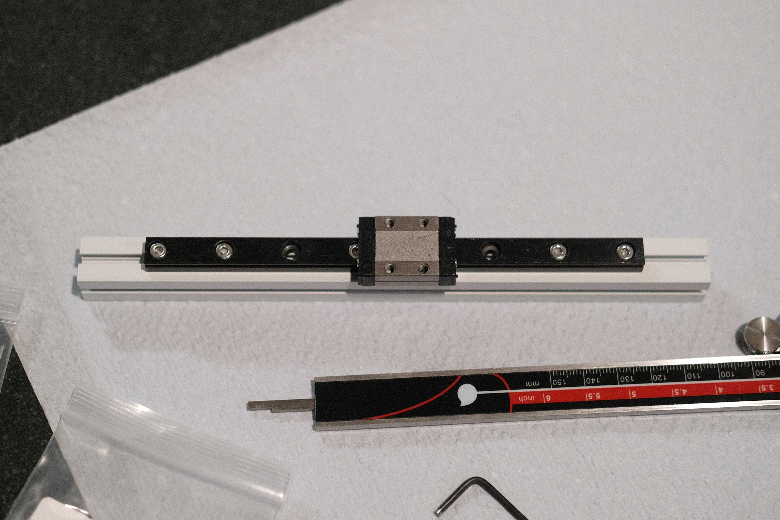
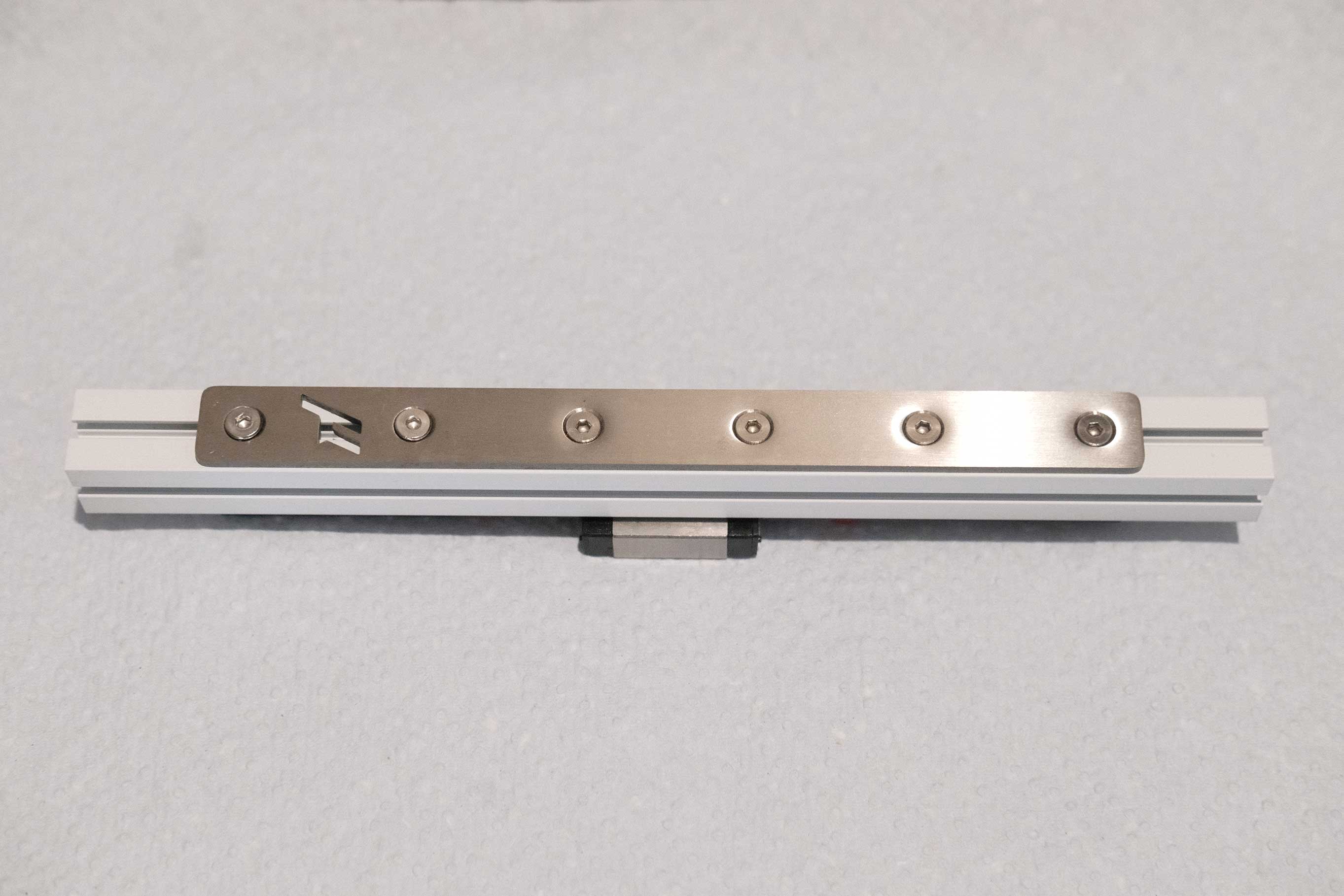
Add the remaining screws. I like to start on the ends and work my way to the center, skipping every other one. In this case, the two in the very center both end up filled.
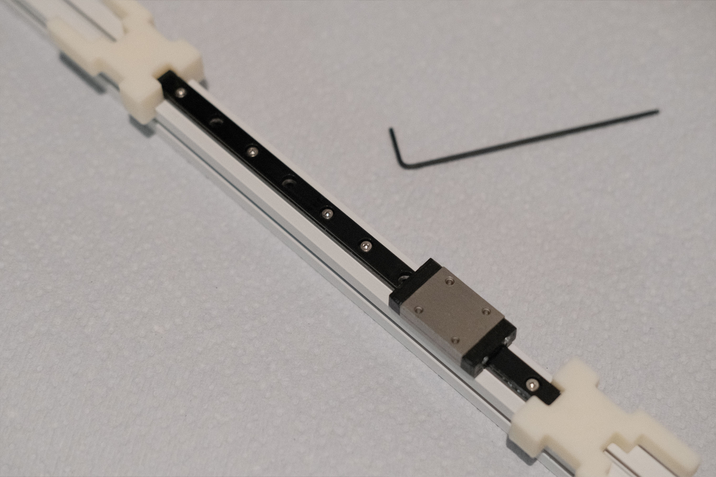 Add the Remaining Screws
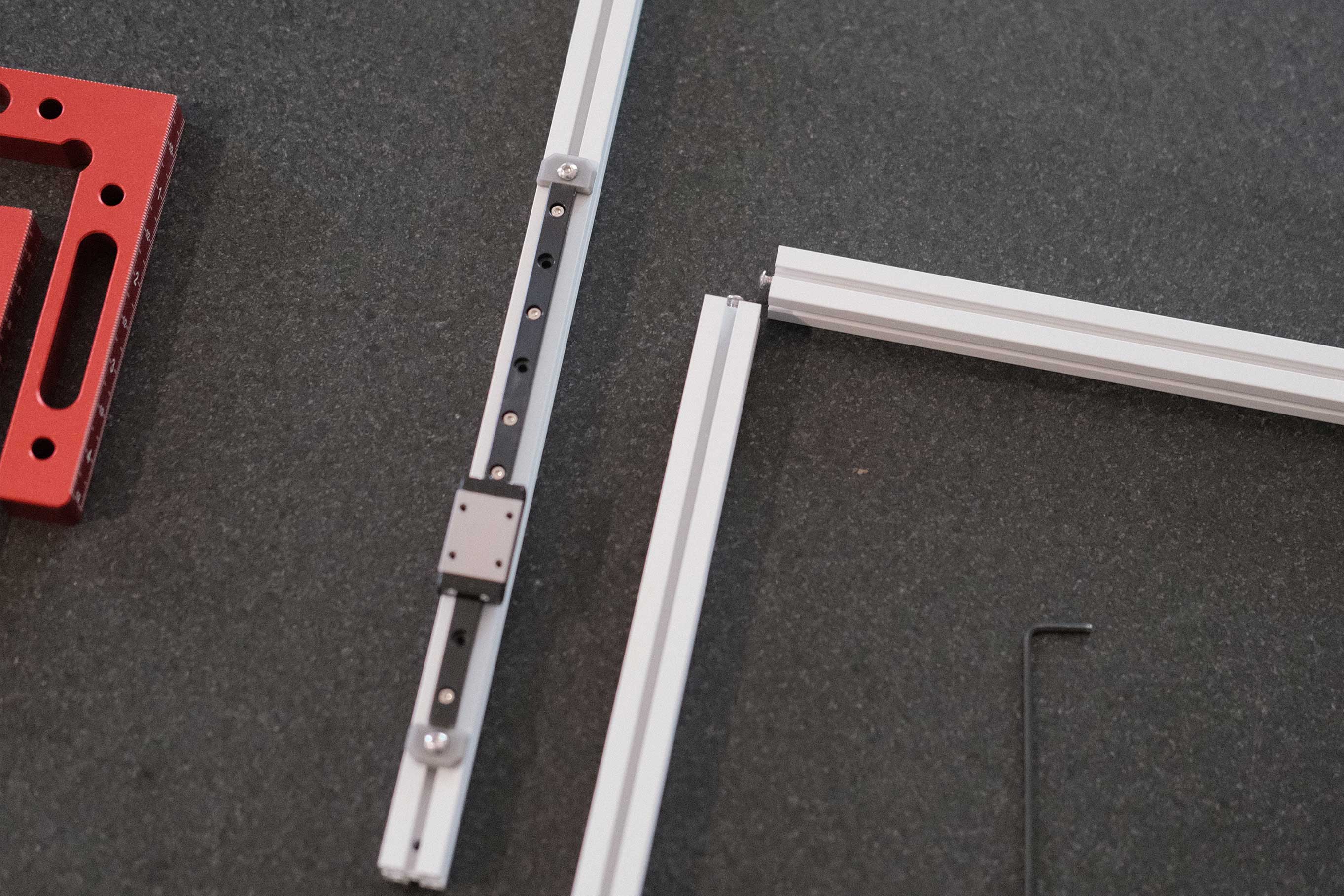
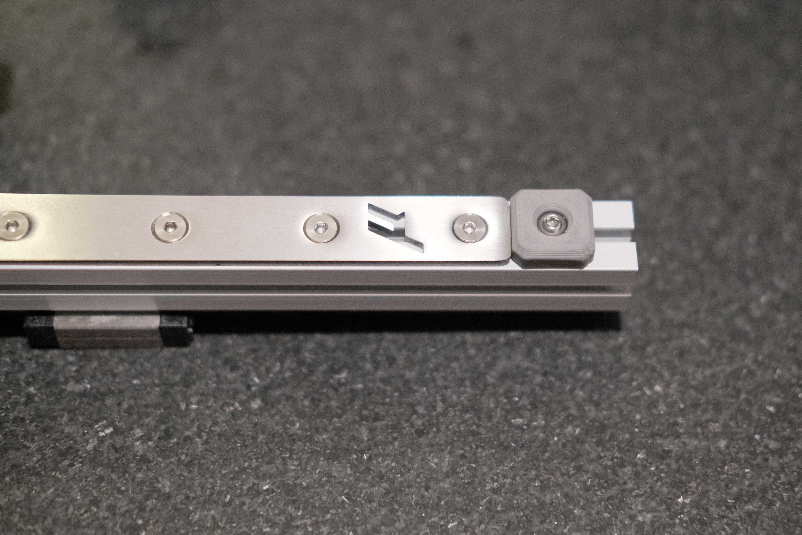
Slide in M3 nuts from both ends of the aluminum extrusion and secure the printed end stops with M3x8 BHCS.
 Add the Rail Stops
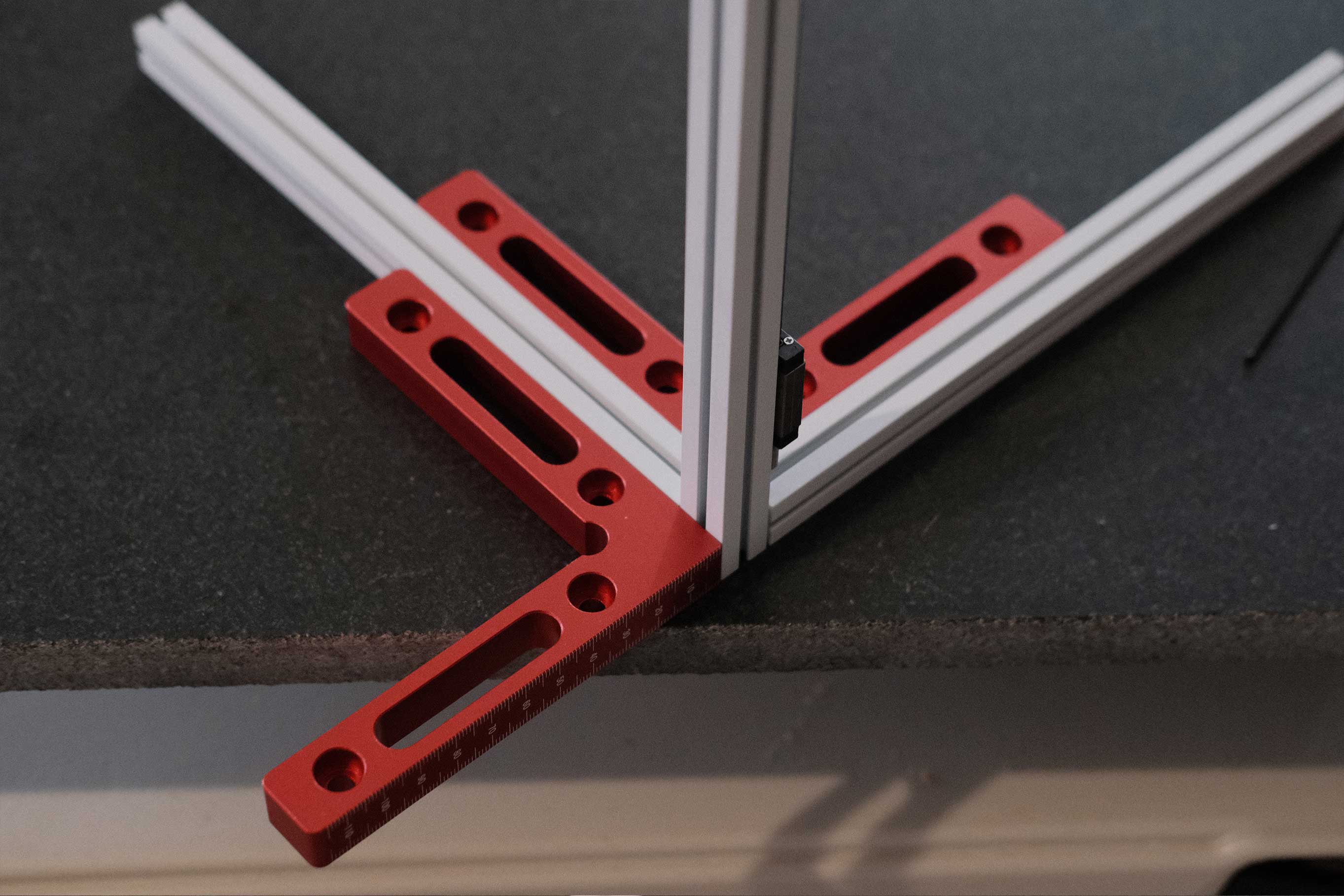
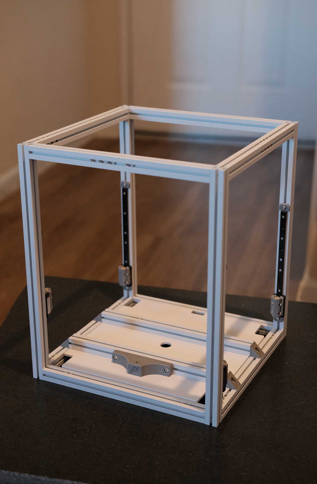
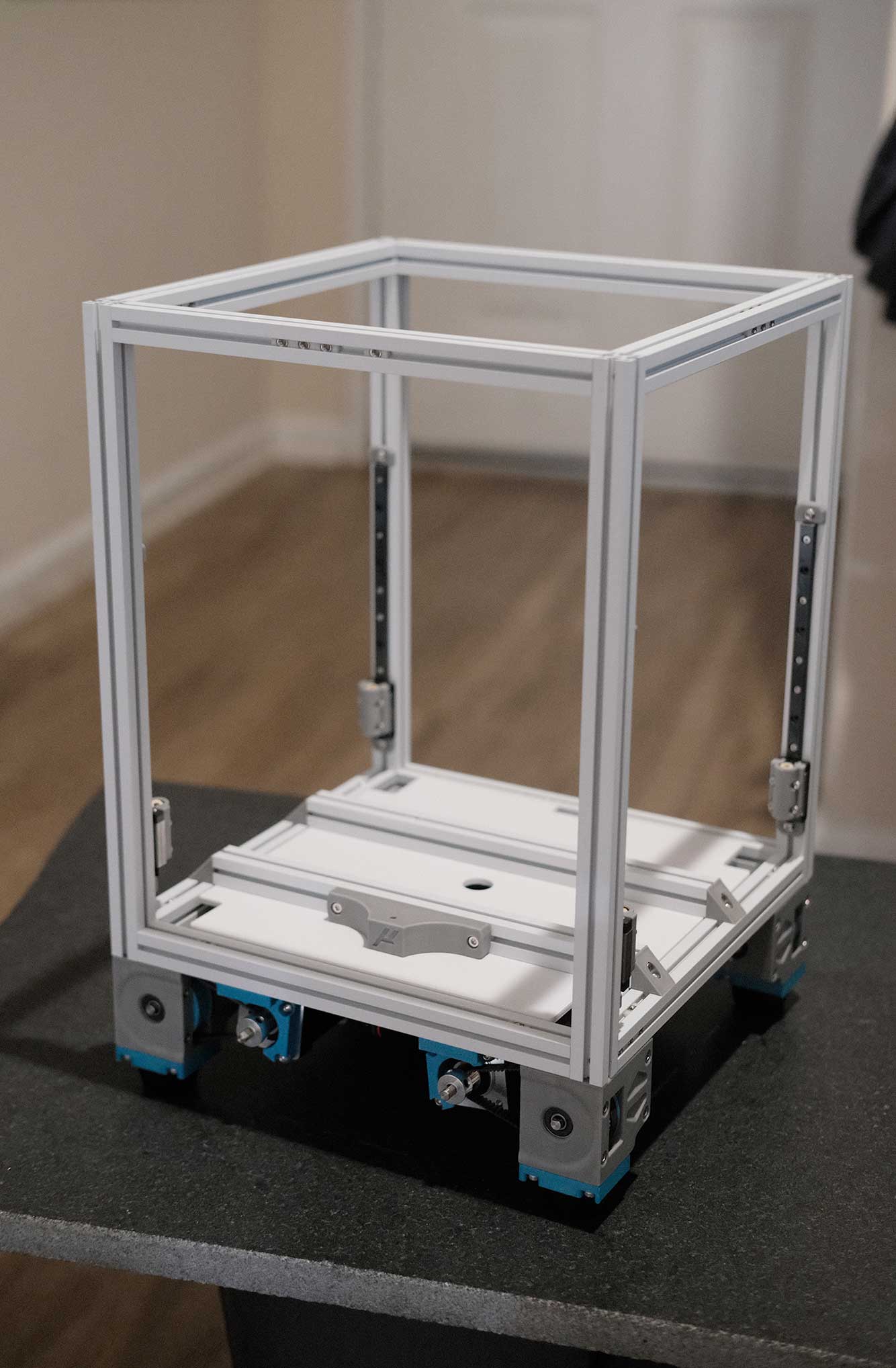
Assembling the Frame
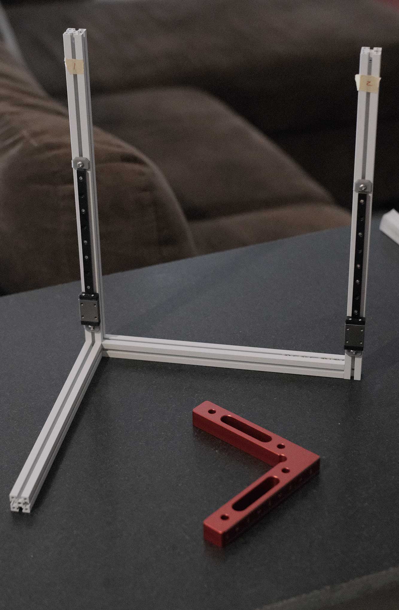
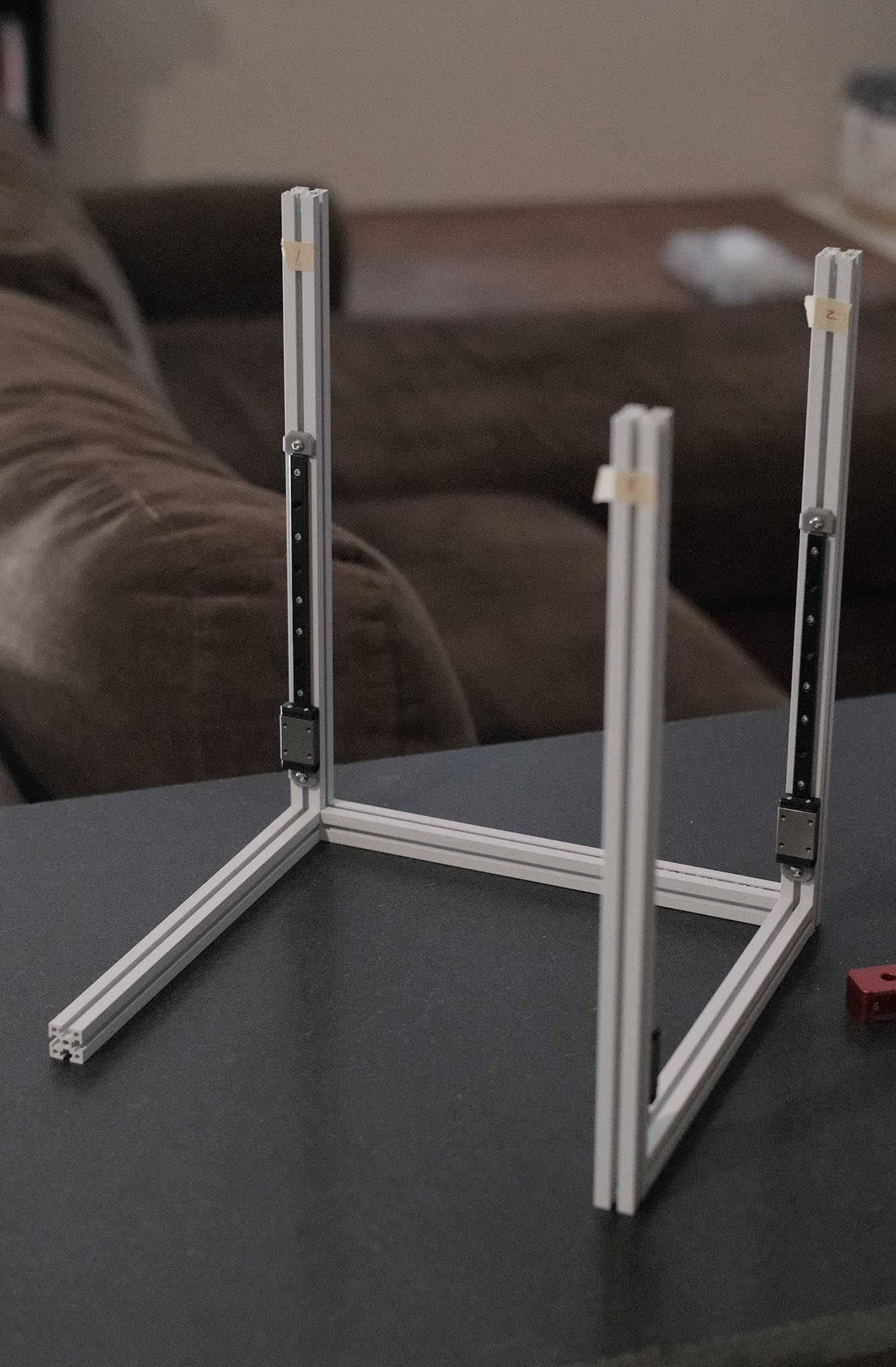
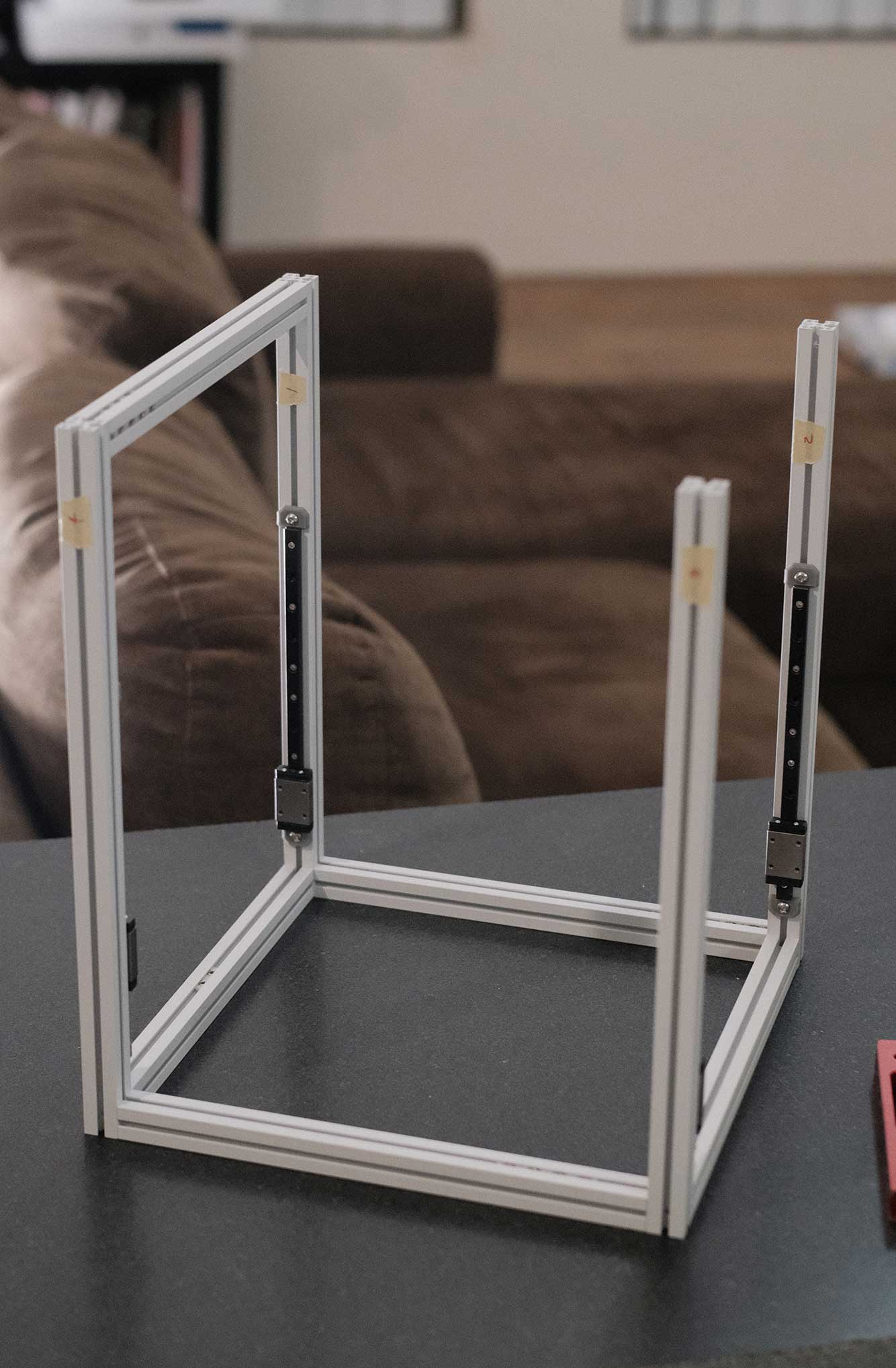
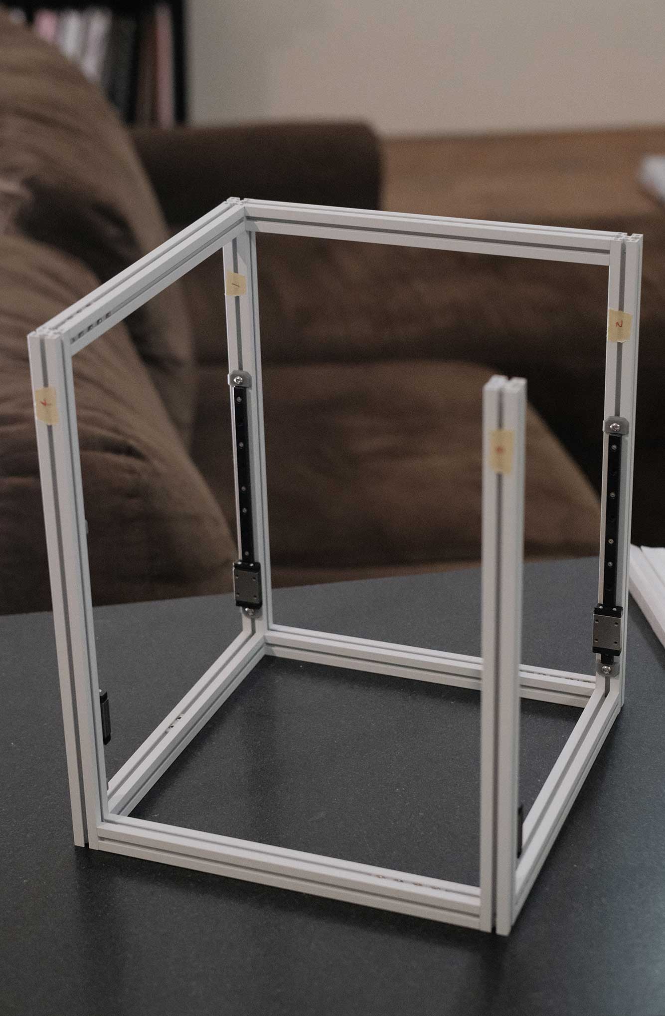
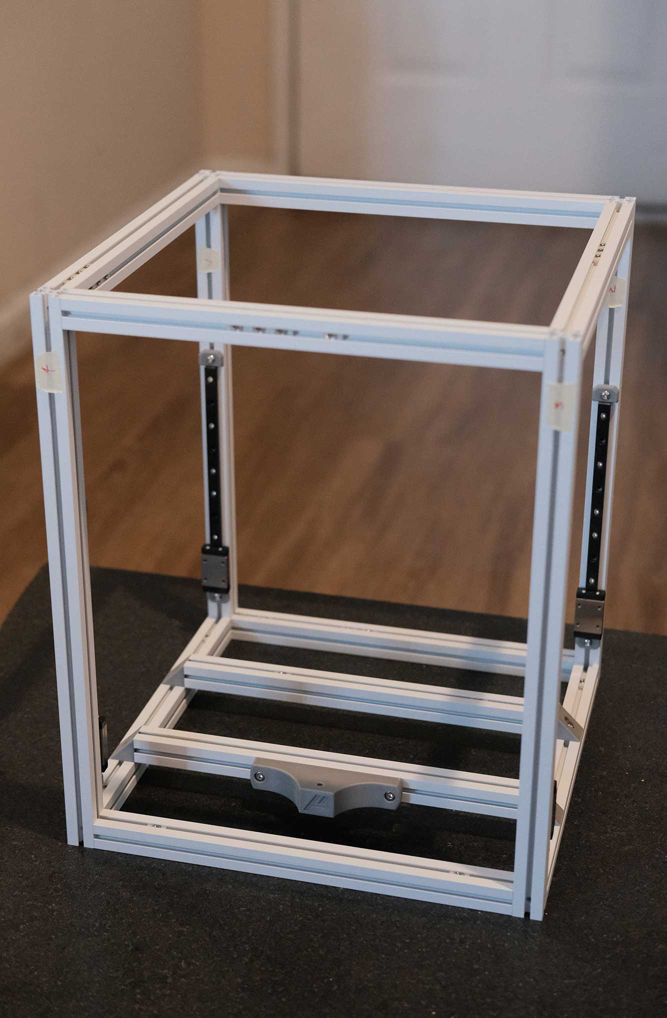
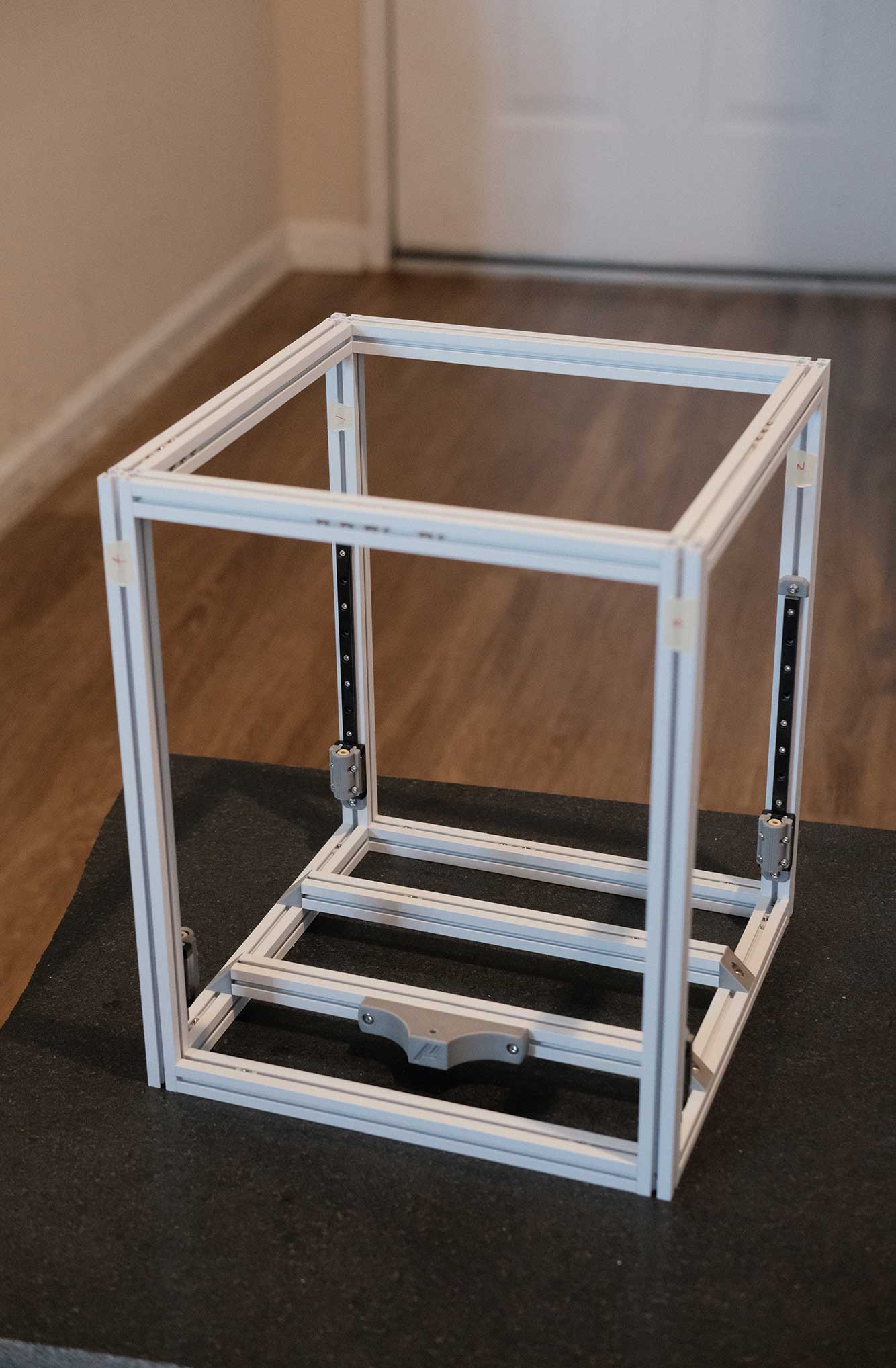
Standard blind-joint assembly. Remember that the vertical members with the linear rails touch the table, and the rails are on the lower half.
 Frame Assembly - 1
 Frame Assembly - 2
 Frame Assembly - 3
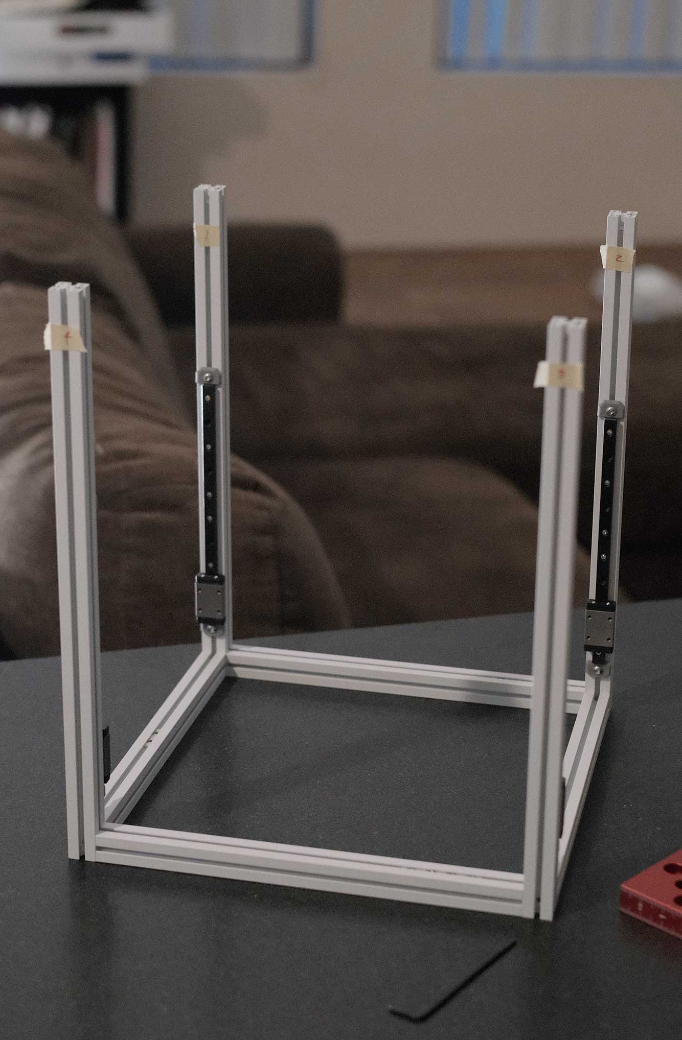
Make sure to pre-insert any necessary M3 nuts as you go. It’s not possible to add them later without some disassembly. In my case, because (1) I’m using a v0.1 aluminum bed with 3-hole mounting and (2) using the leftover 10x11 cable chain from my Trident build, the amount of nuts will not match the manual. This is a good time to add nuts for future mods as well.
 Frame Assembly - 4
 Frame Assembly - 5
 Frame Assembly - 6
 Frame Assembly - 7
 Frame Assembly - 8
 Frame Assembly - 9
 Frame Assembly - 10
 Frame Assembly - 11
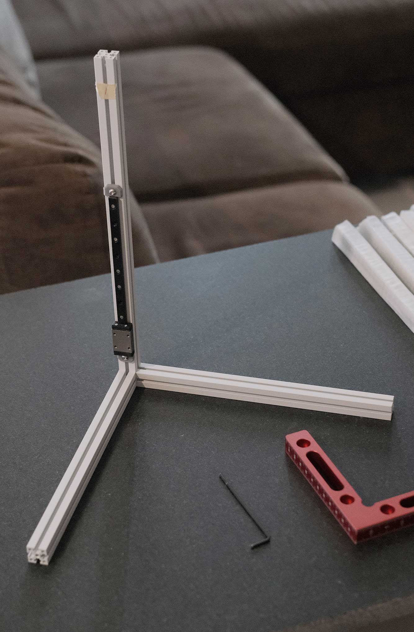
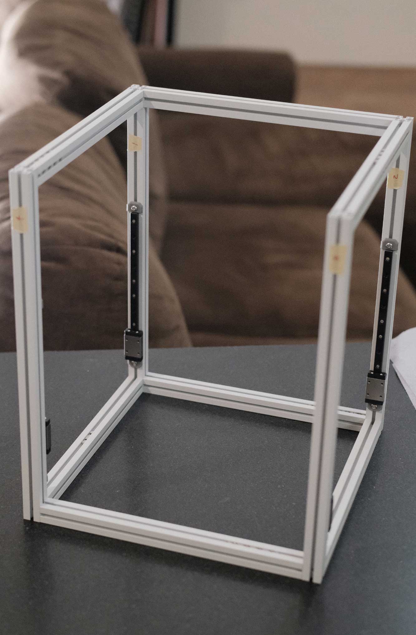
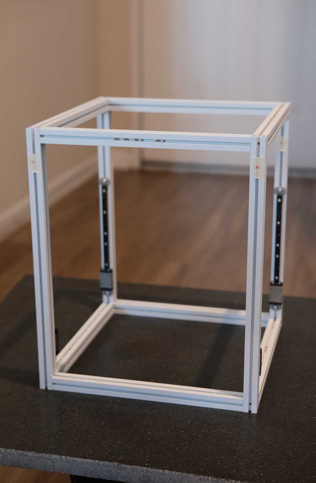
Now that the basic frame is assembled, this is a good time to check for squareness. For each face, measure the two diagonals to see if they are within 1mm of each other. For the bottom, check to make sure it’s not rocking.
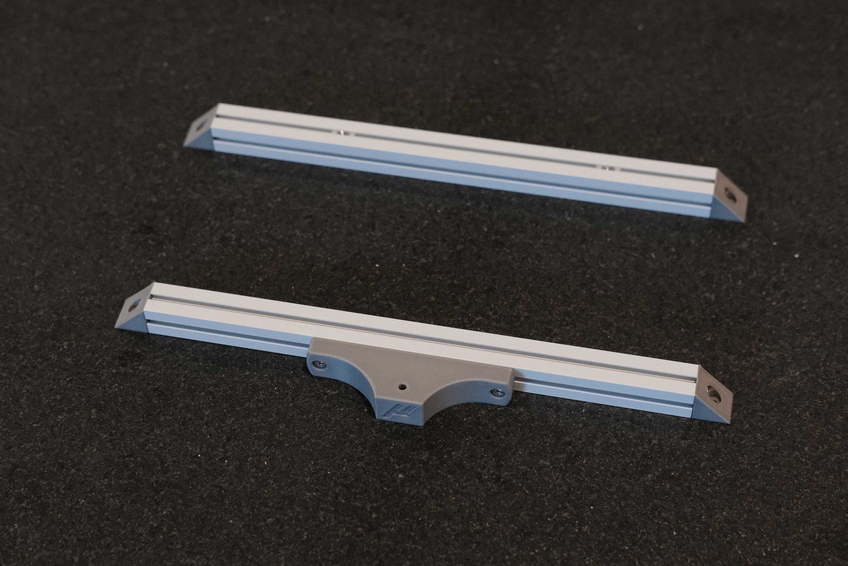
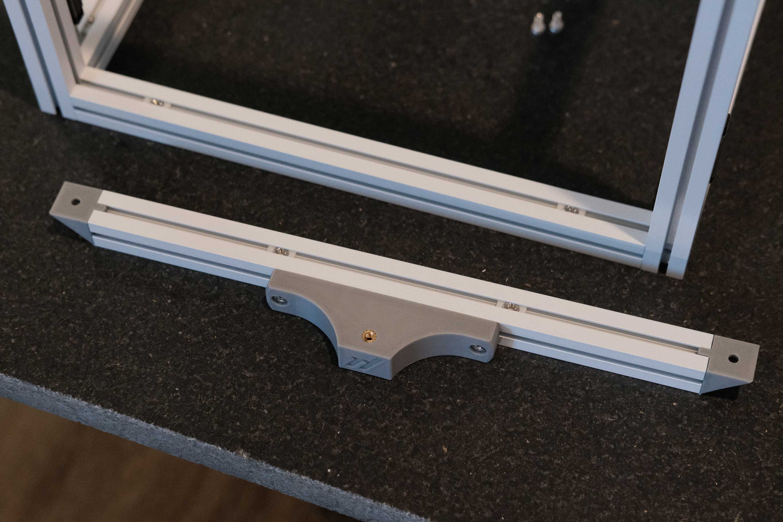
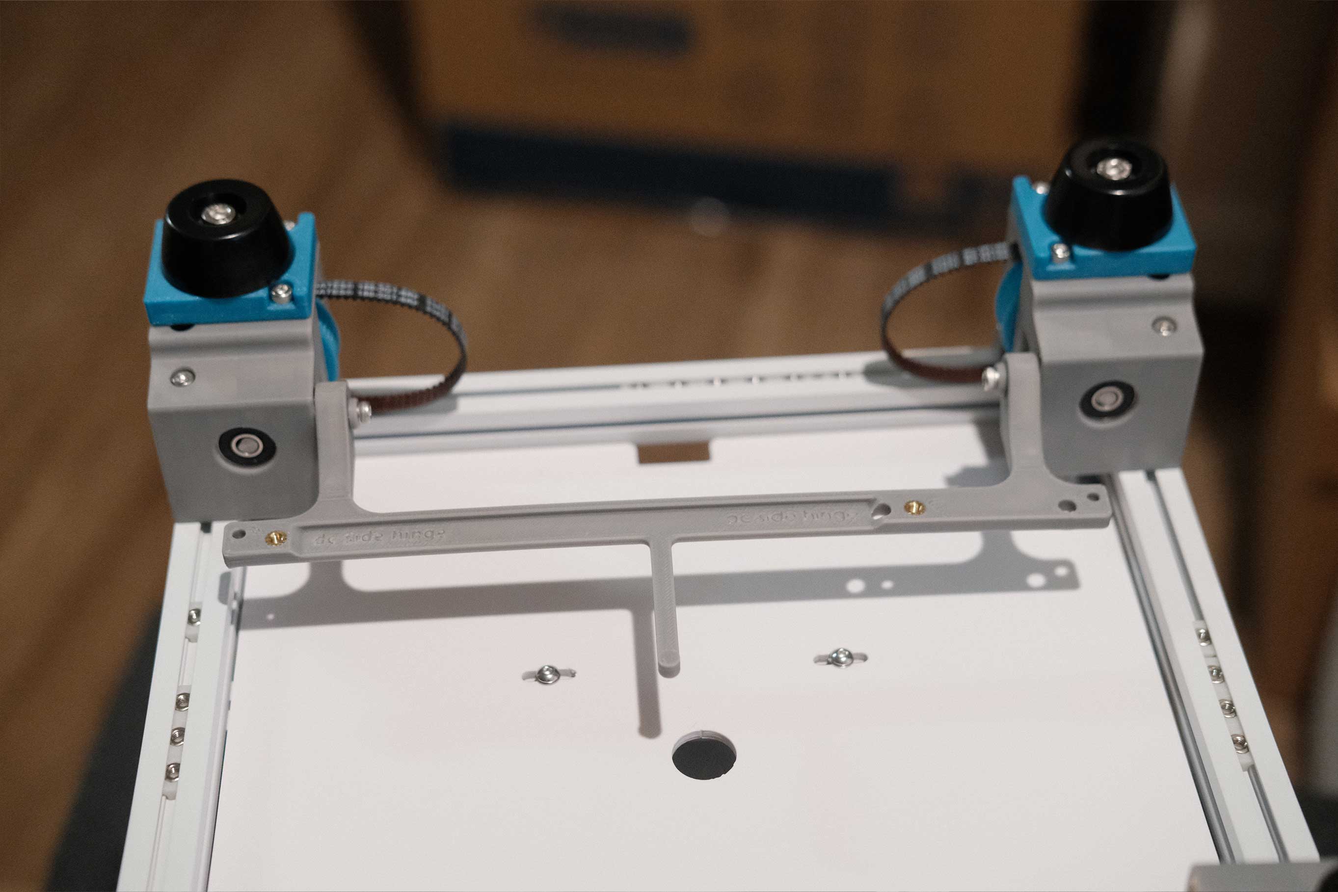
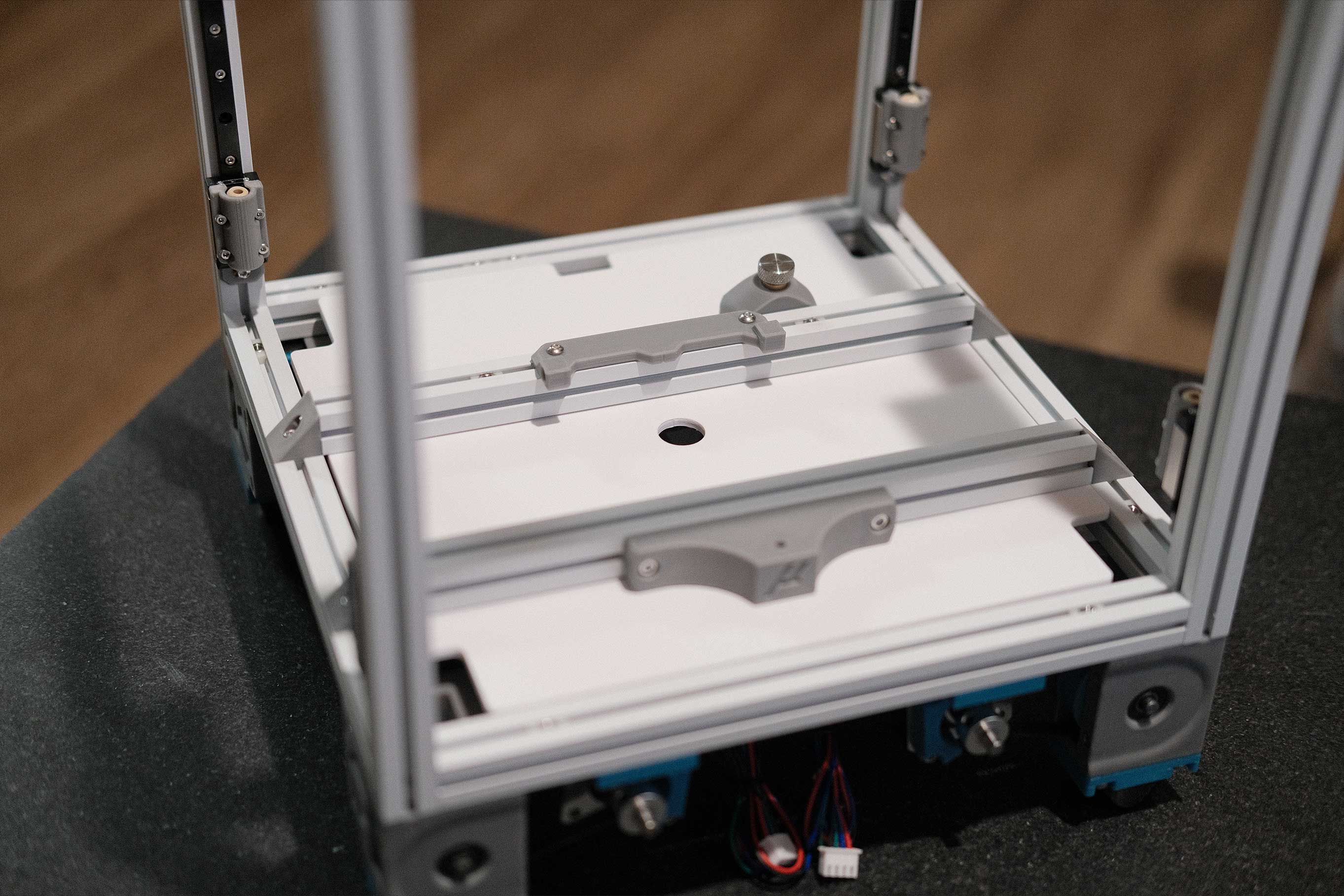
The PrecisePrinterParts v0.1 bed that I am using has 3-point mounting, while the latest iteration of the Micron design has 4-point mounting like the v2.4. It’s possible to re-drill (there are even drill guides in the STL folder), but I only have hand tools and would prefer not to mangle it. Instead, I’m prepping these bed extrusions like the earlier Micron design, horizontally with a front printed piece to line up with the front mounting hole. A nice benefit is this horizontal mounting makes it compatible with Zruncho’s ZeroFilters.
Update: With the Zerofilters placed, the extrusions are pushed apart just a tiny bit, making the mounting hole in the front printed piece too far. I needed to adjust the model and reprint.
 Frame Assembly - 12
Don’t forget this heatset insert on the bottom of the front piece.
 Frame Assembly - 13
 Frame Assembly - 14
Z Joints
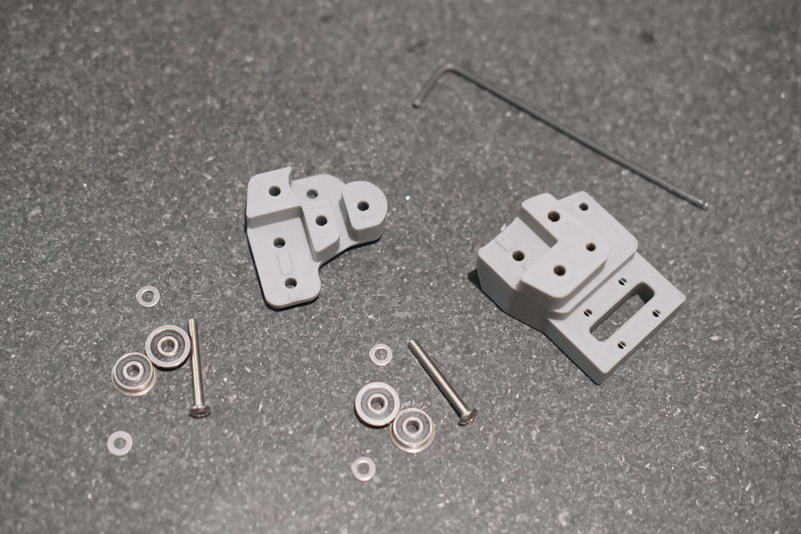
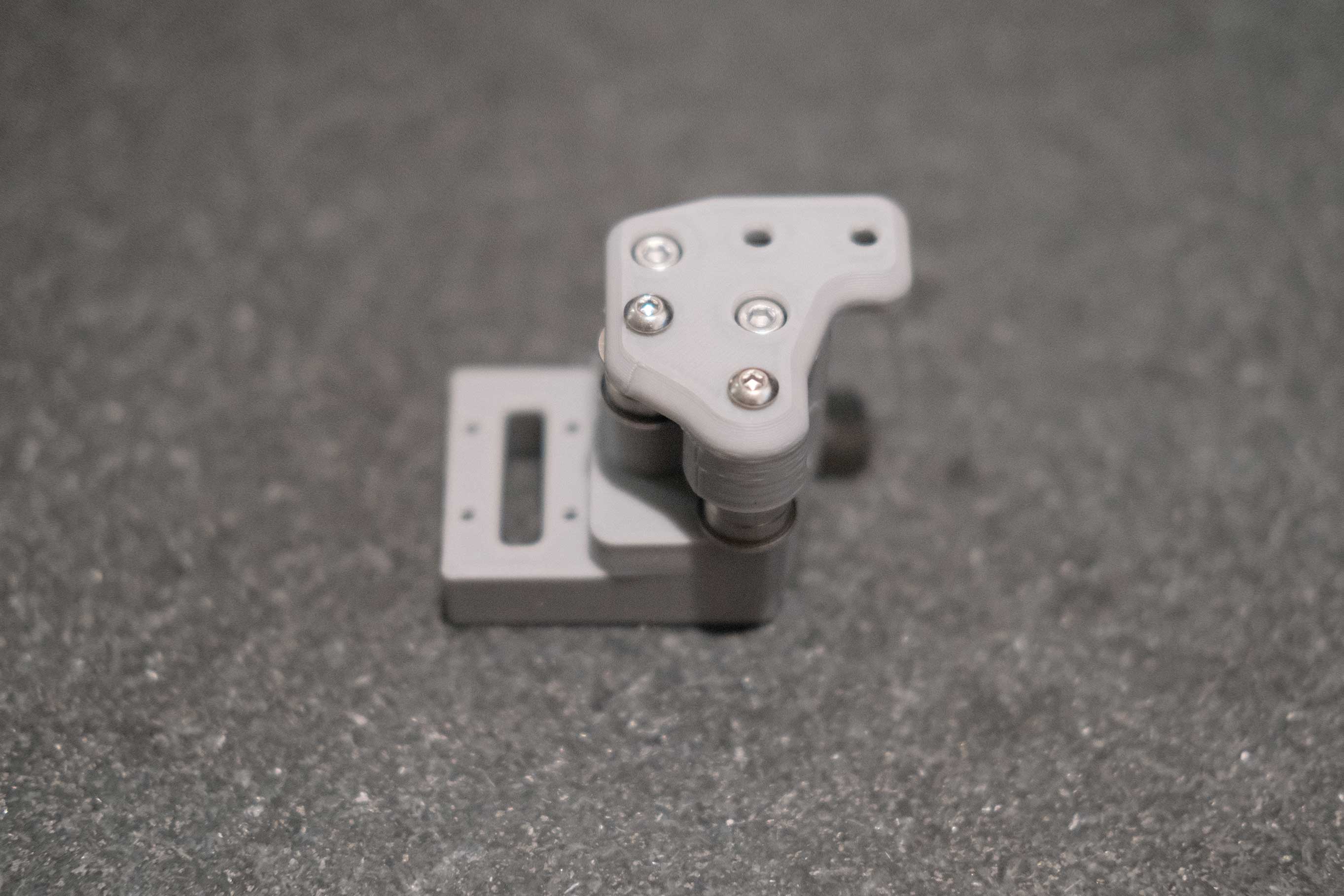
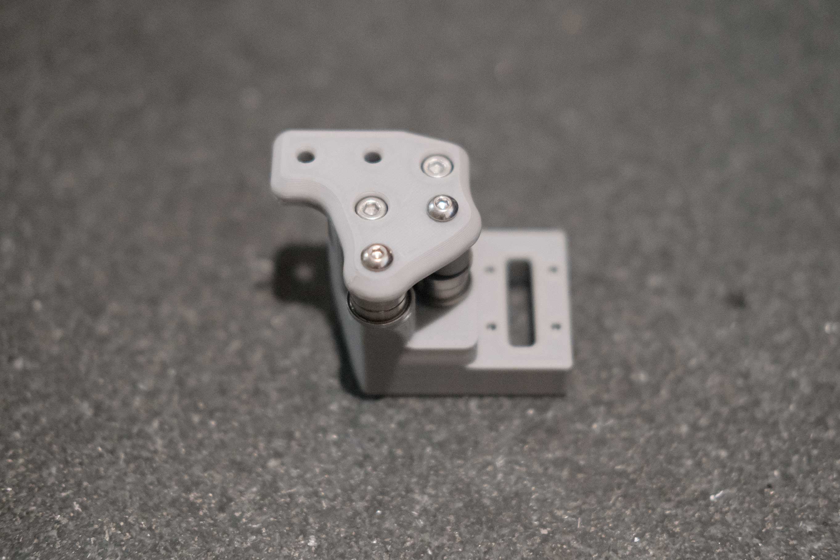
Insert the Igus KGLM-3 spherical bearings into the printed parts and secure each one with 4 M2x6 SHCS. These bearings can rotate in 3 dimensions and allow the gantry to adjust.
 Z Joints - 1
 Z Joints - 2
Deck
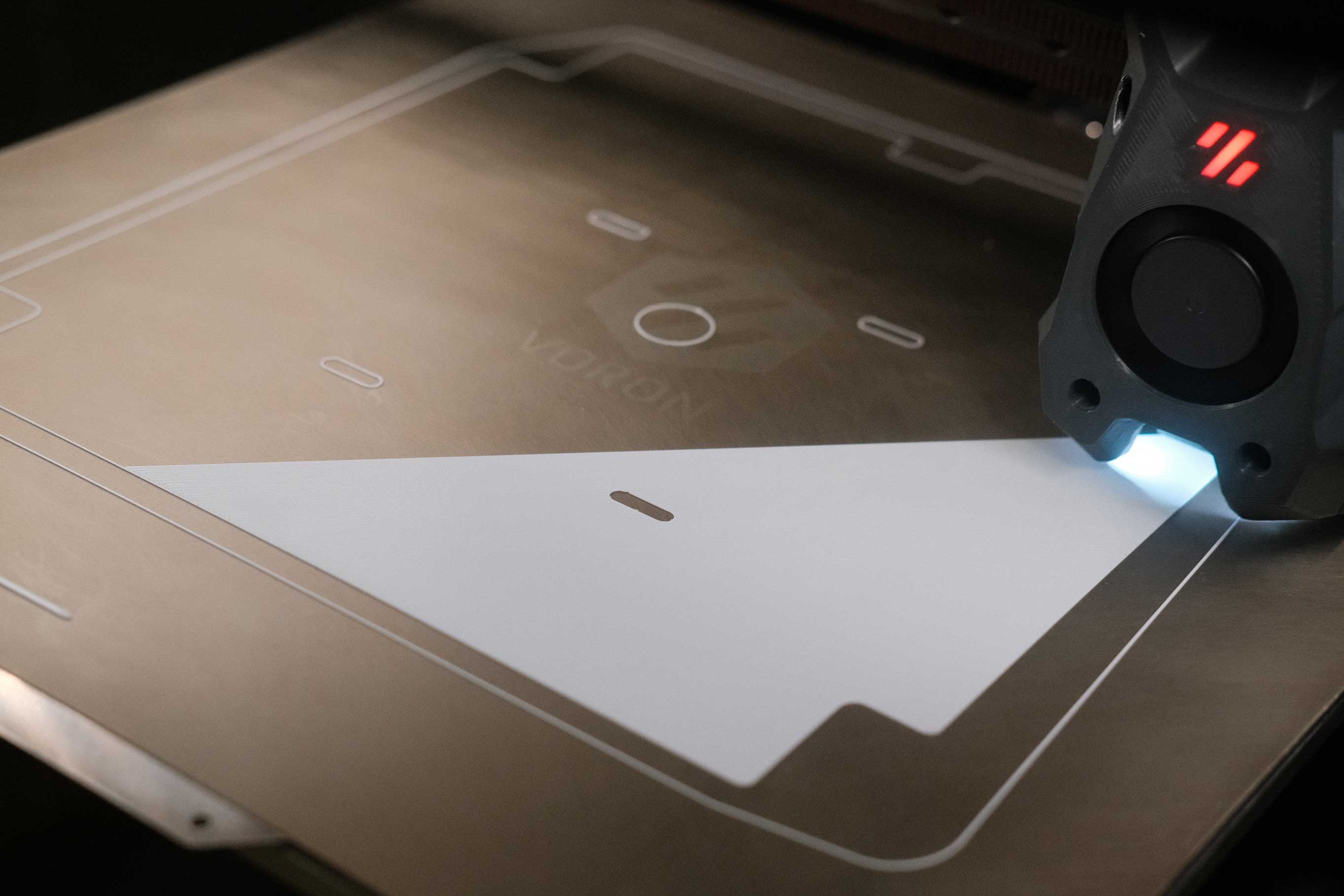
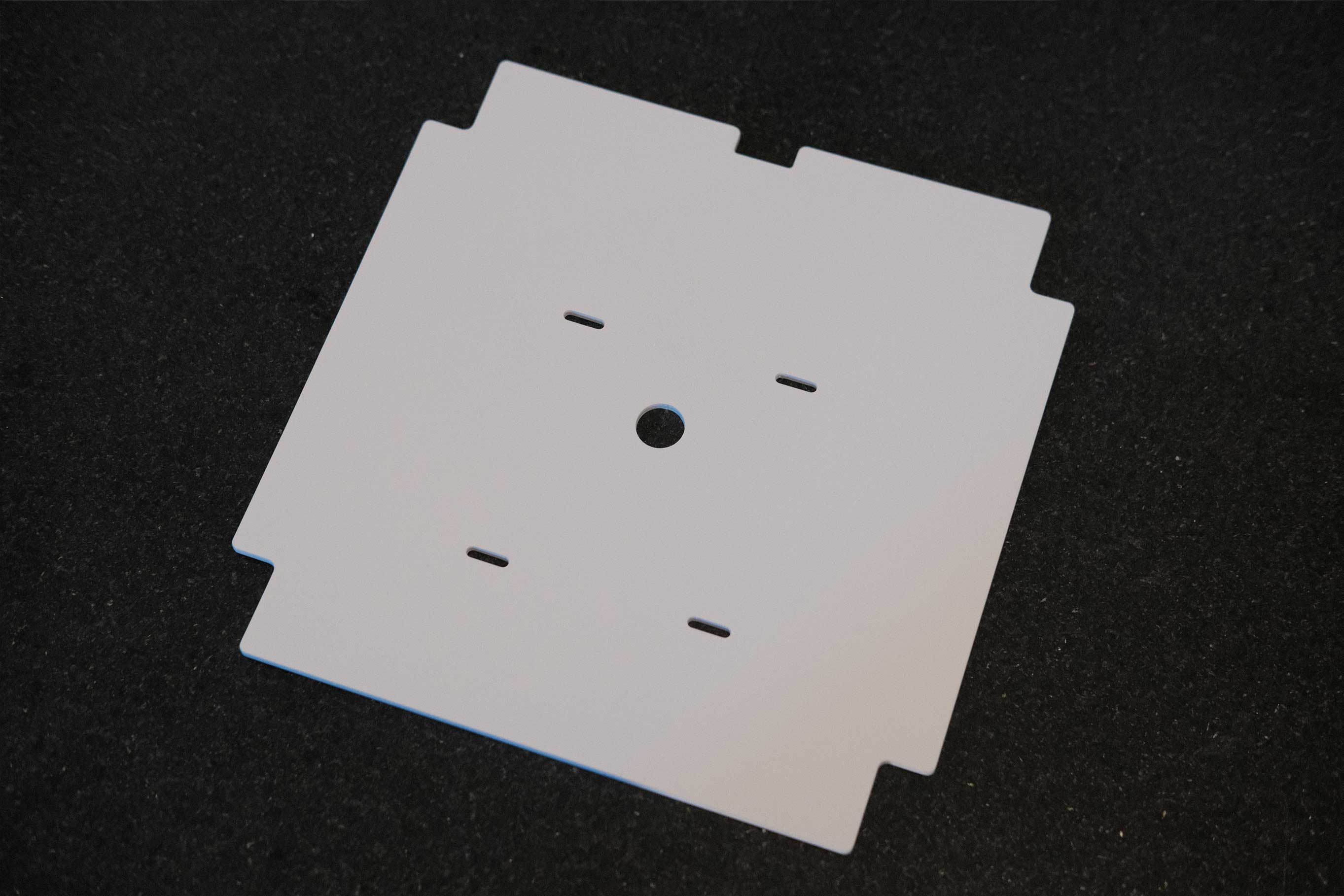
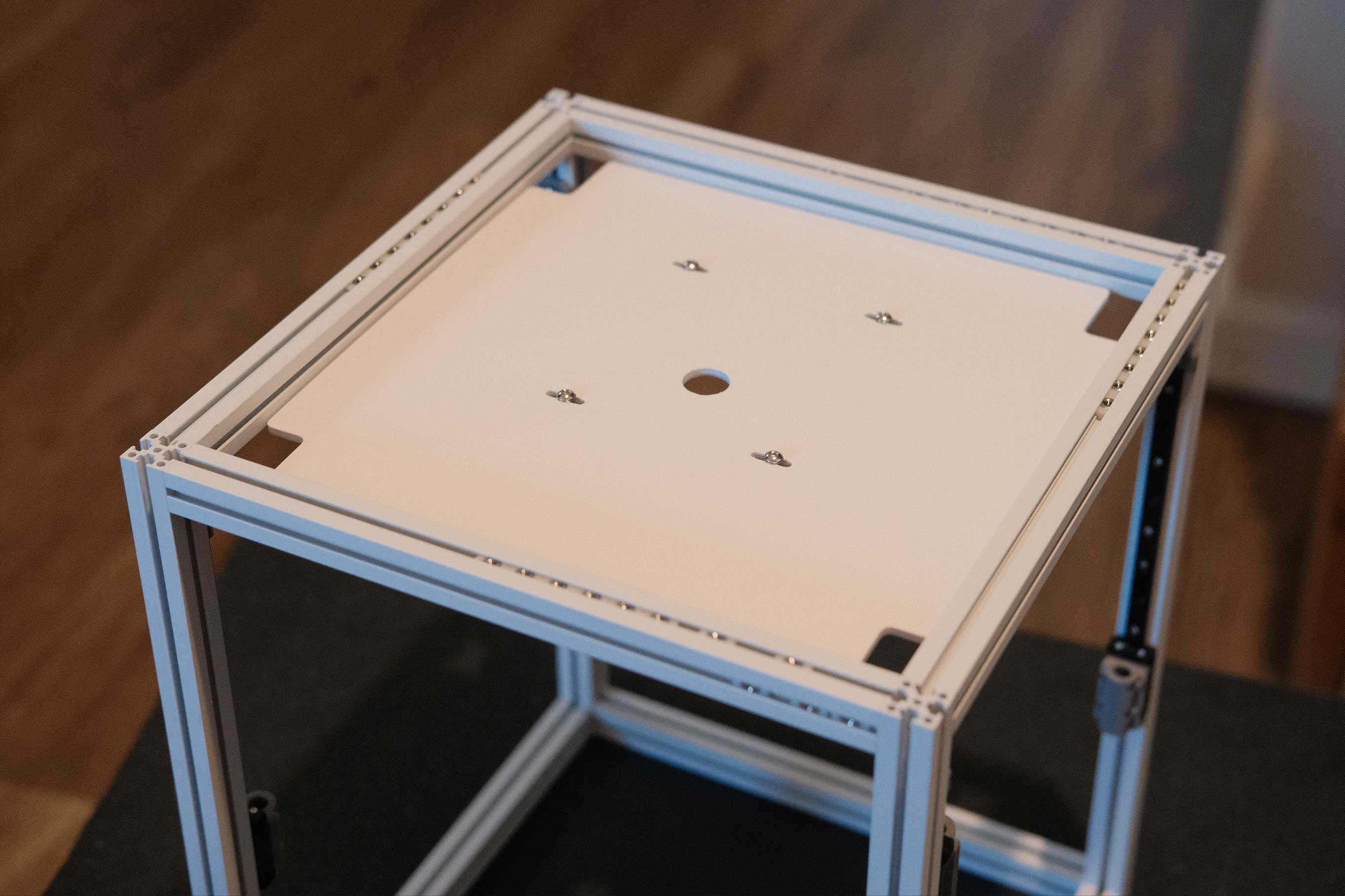
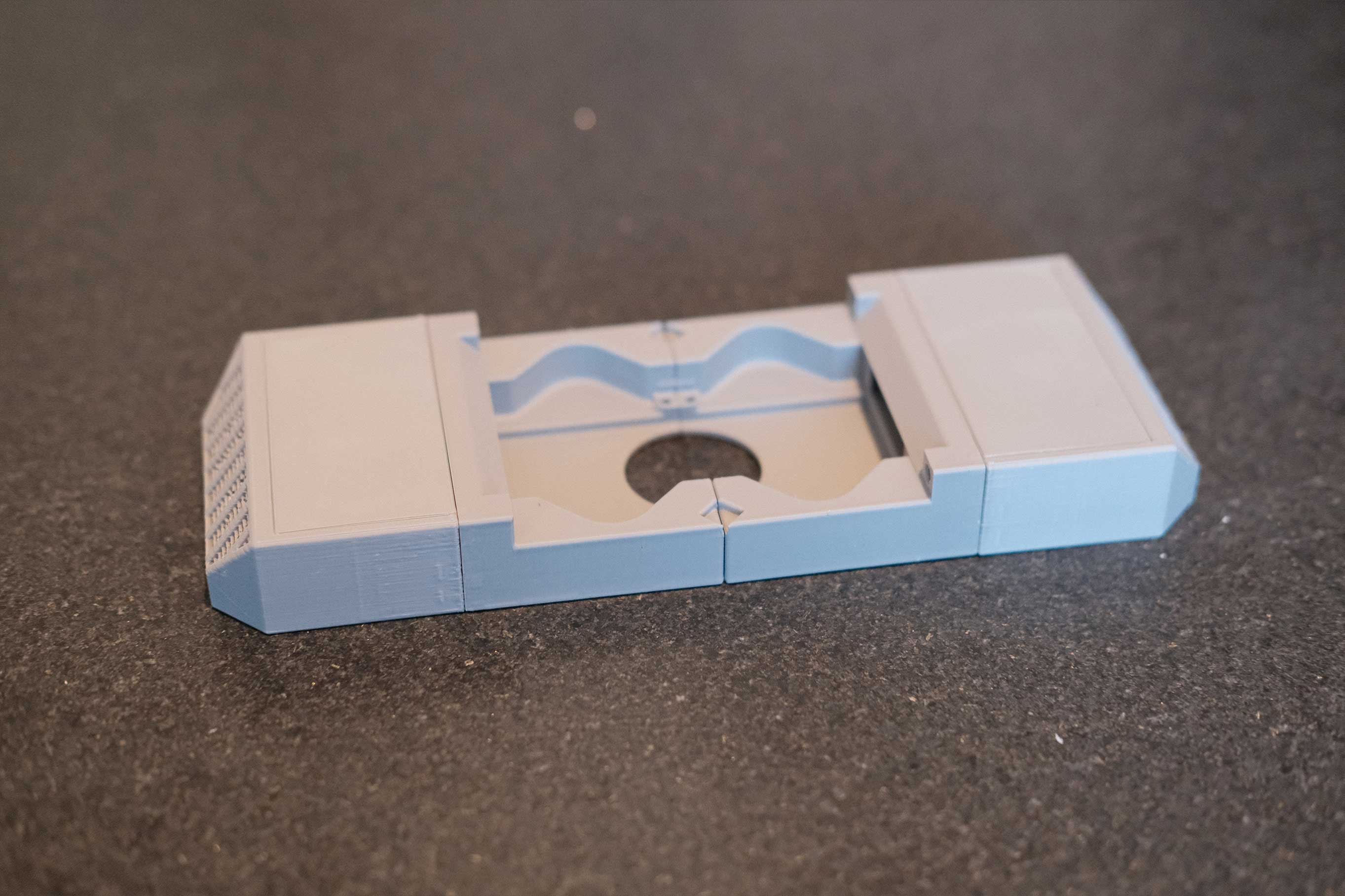
These photos are showing the original design from the Micron STLs folder, but I ended up tweaking the design to center the hole within the ZeroFilters and reducing the corner cutouts for the belts to eliminate gaps.
As an aside, this is the perfect use-case for titanium white, which is infamous for horribly uneven sidewalls.
 Printed Deck - 1
 Printed Deck - 2
 Printed Deck - 3
 Printed Deck - 4
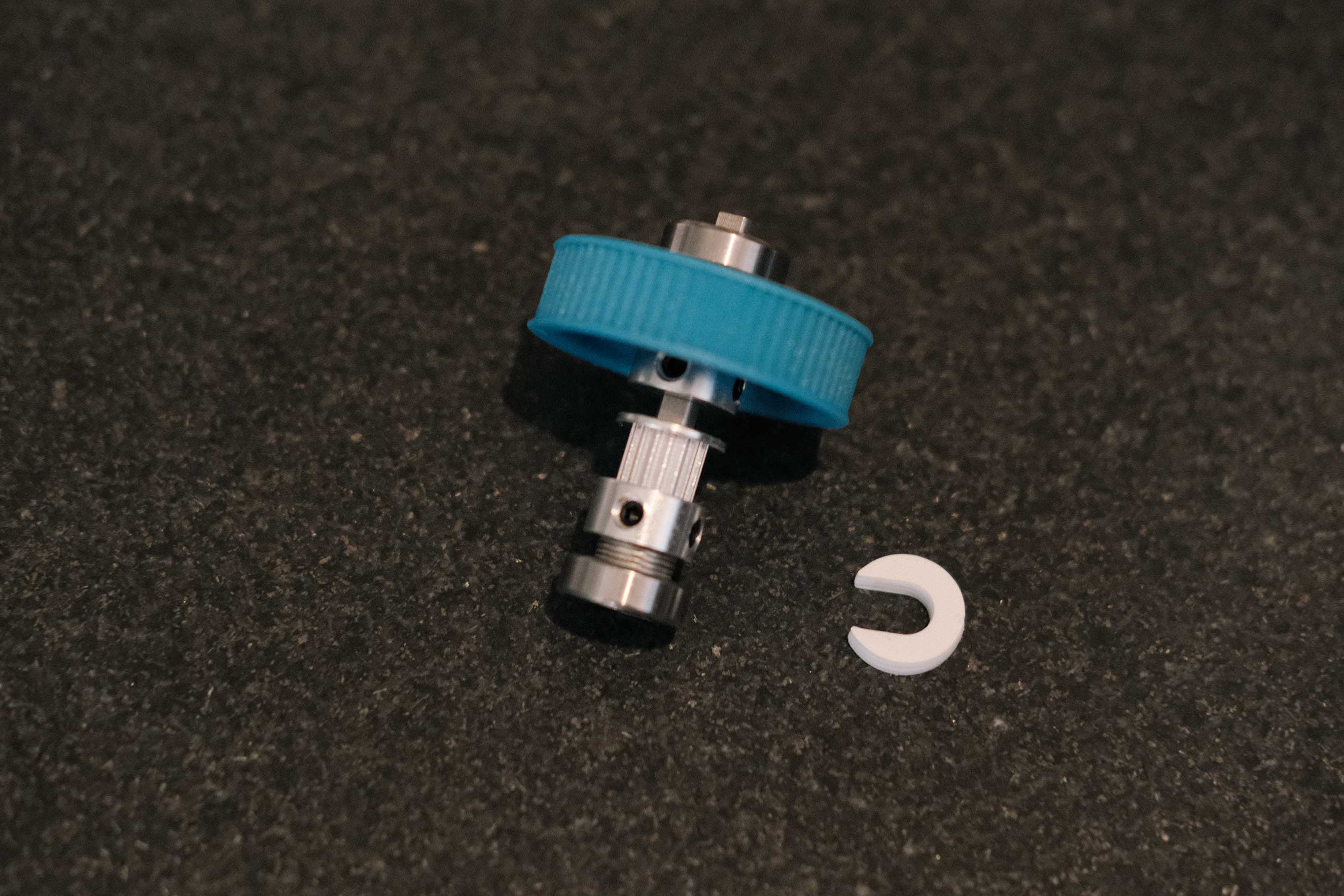
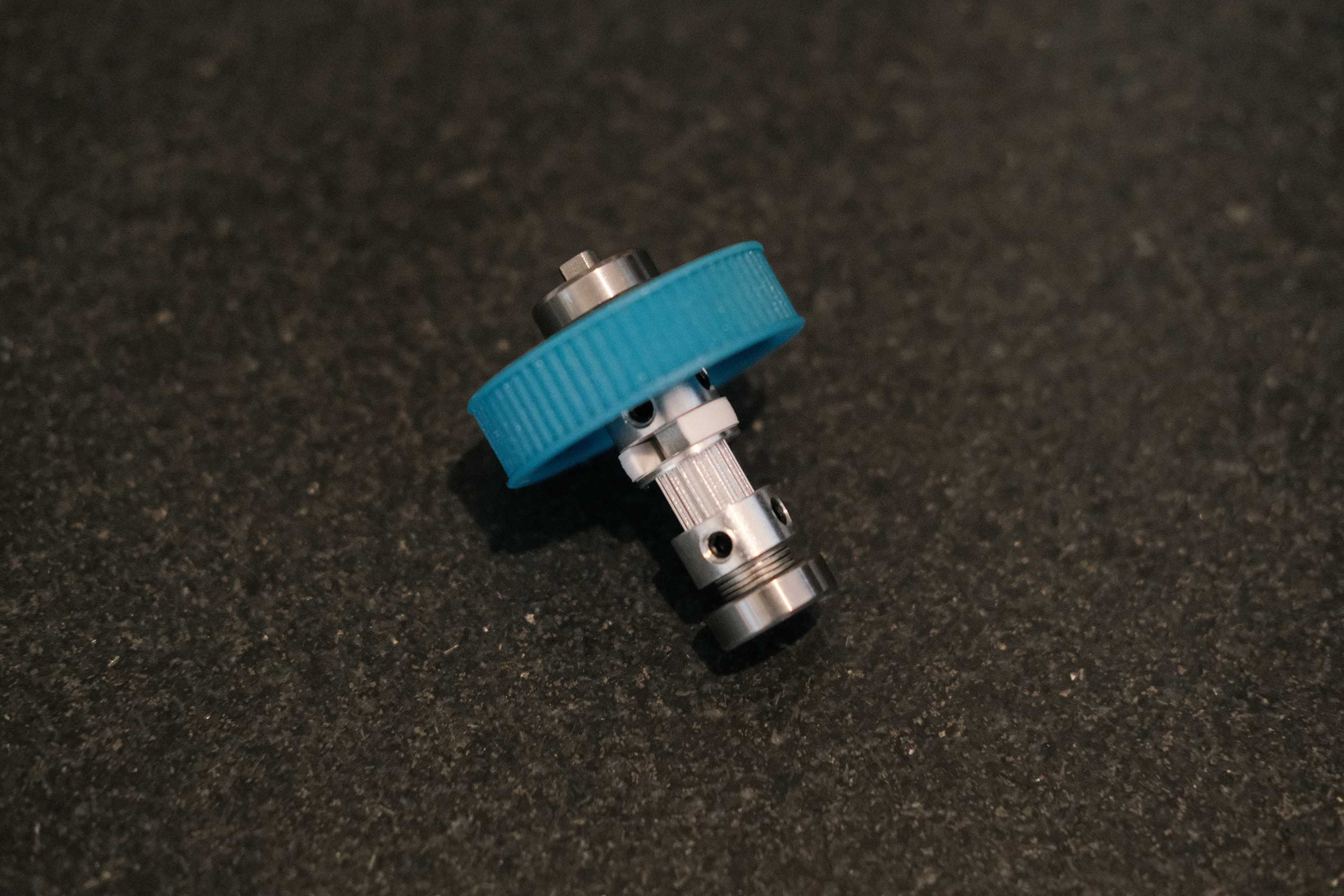
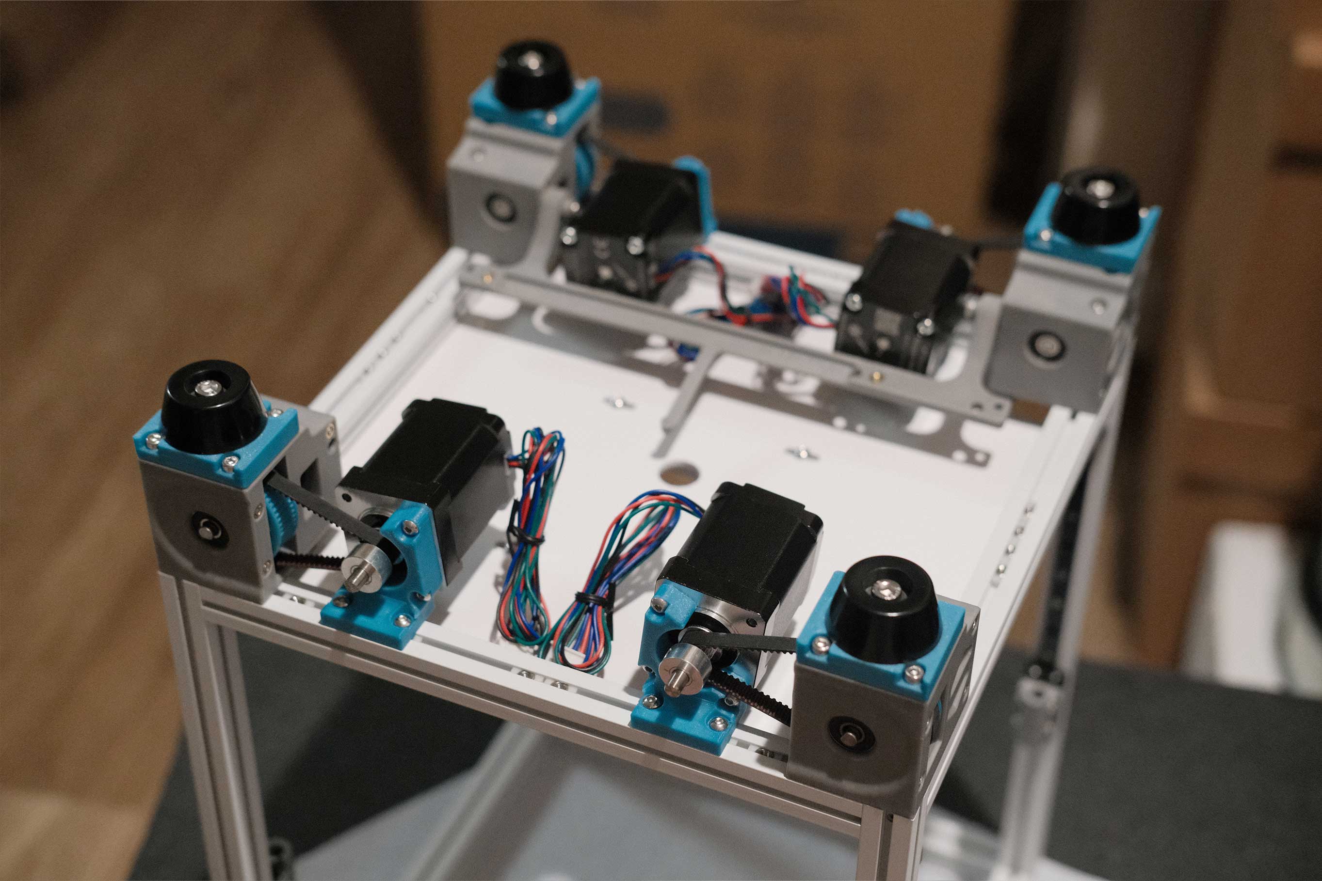
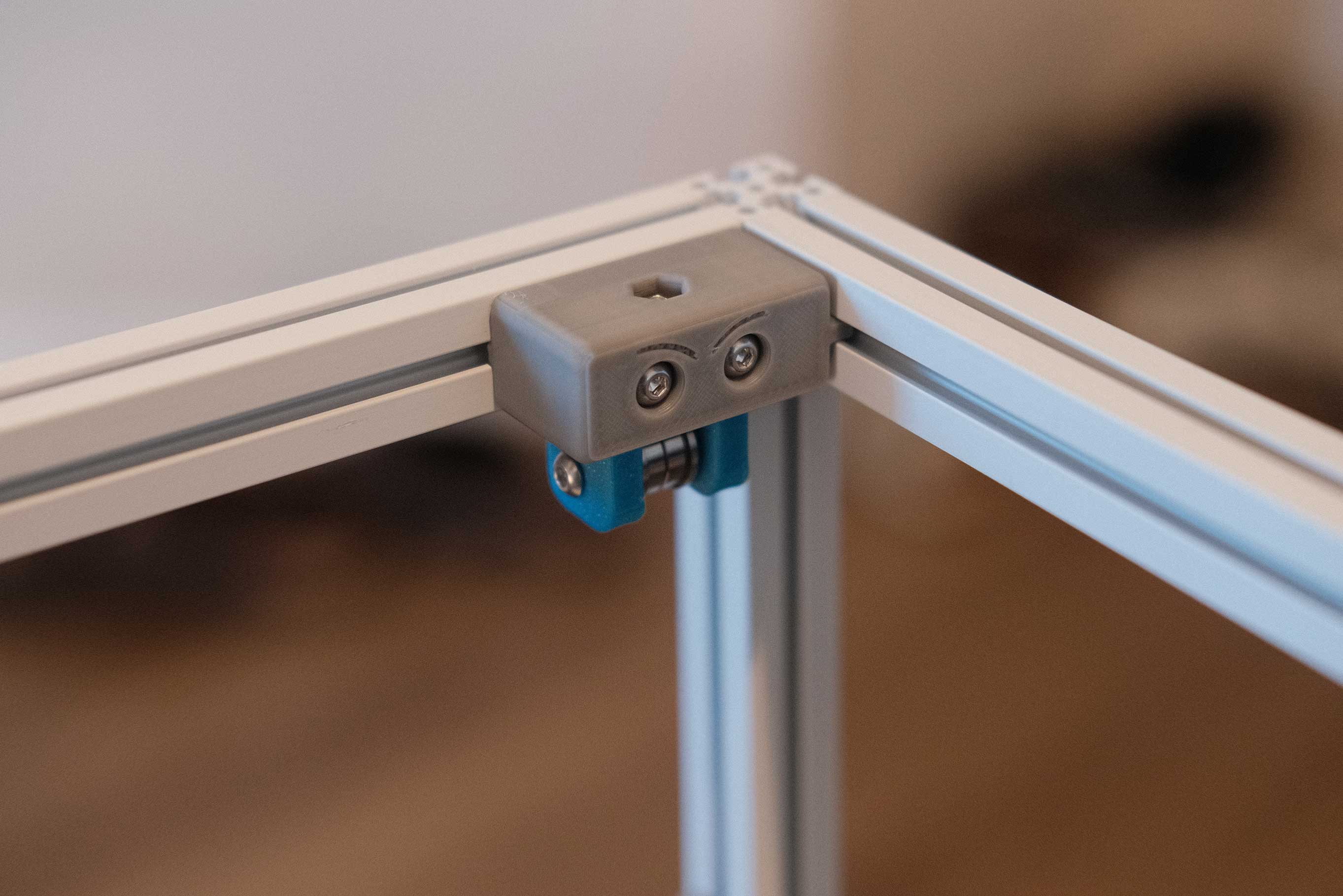
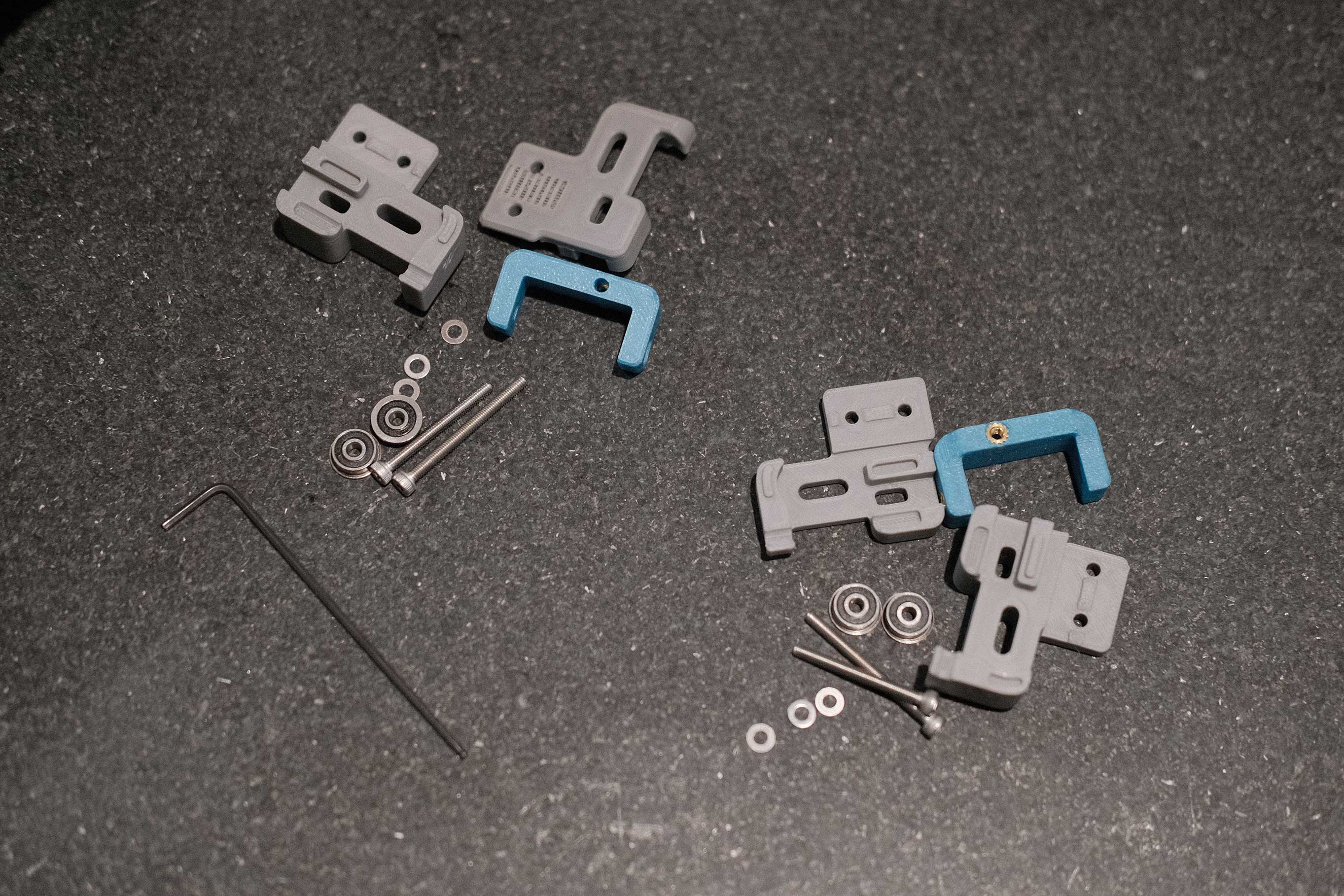
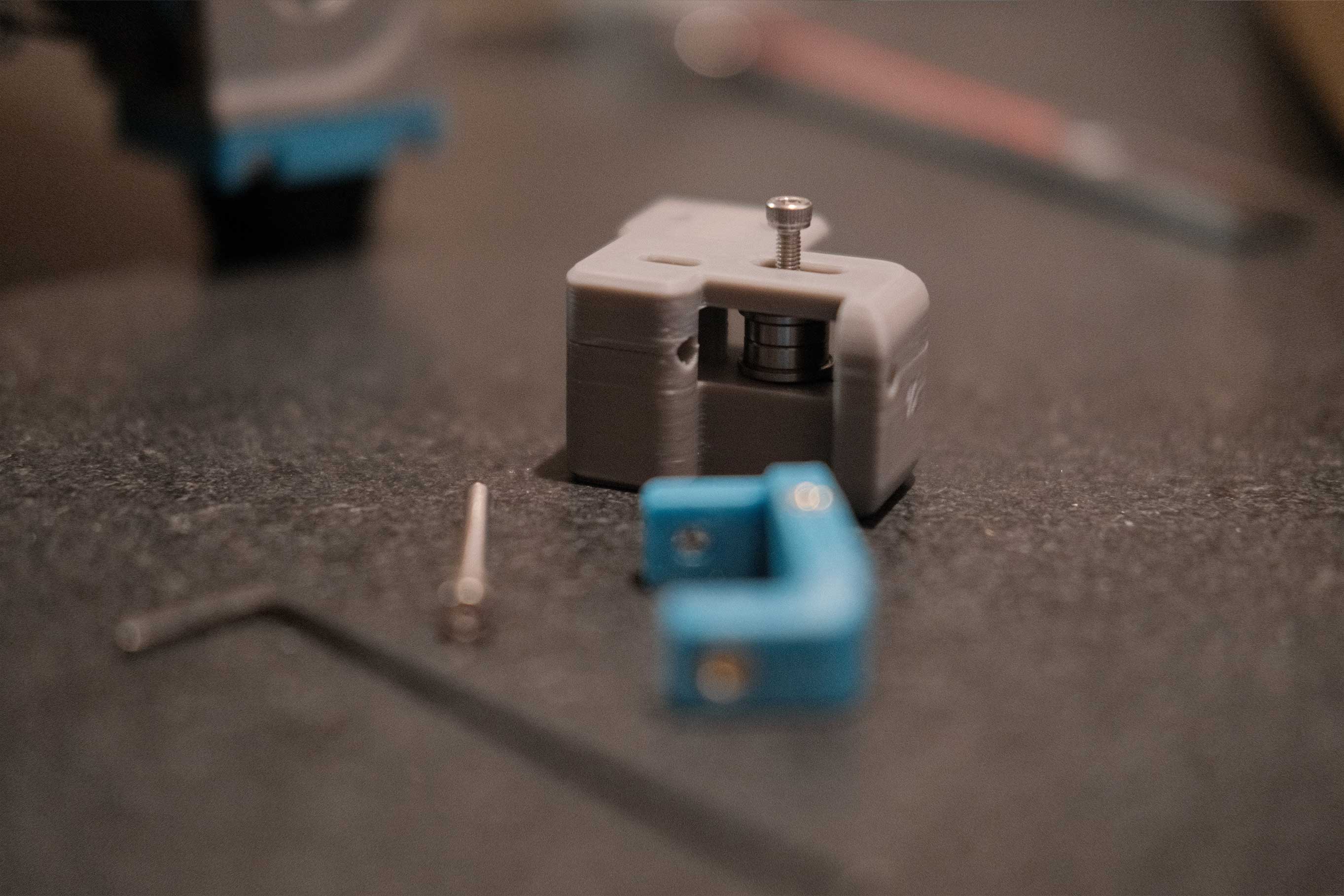
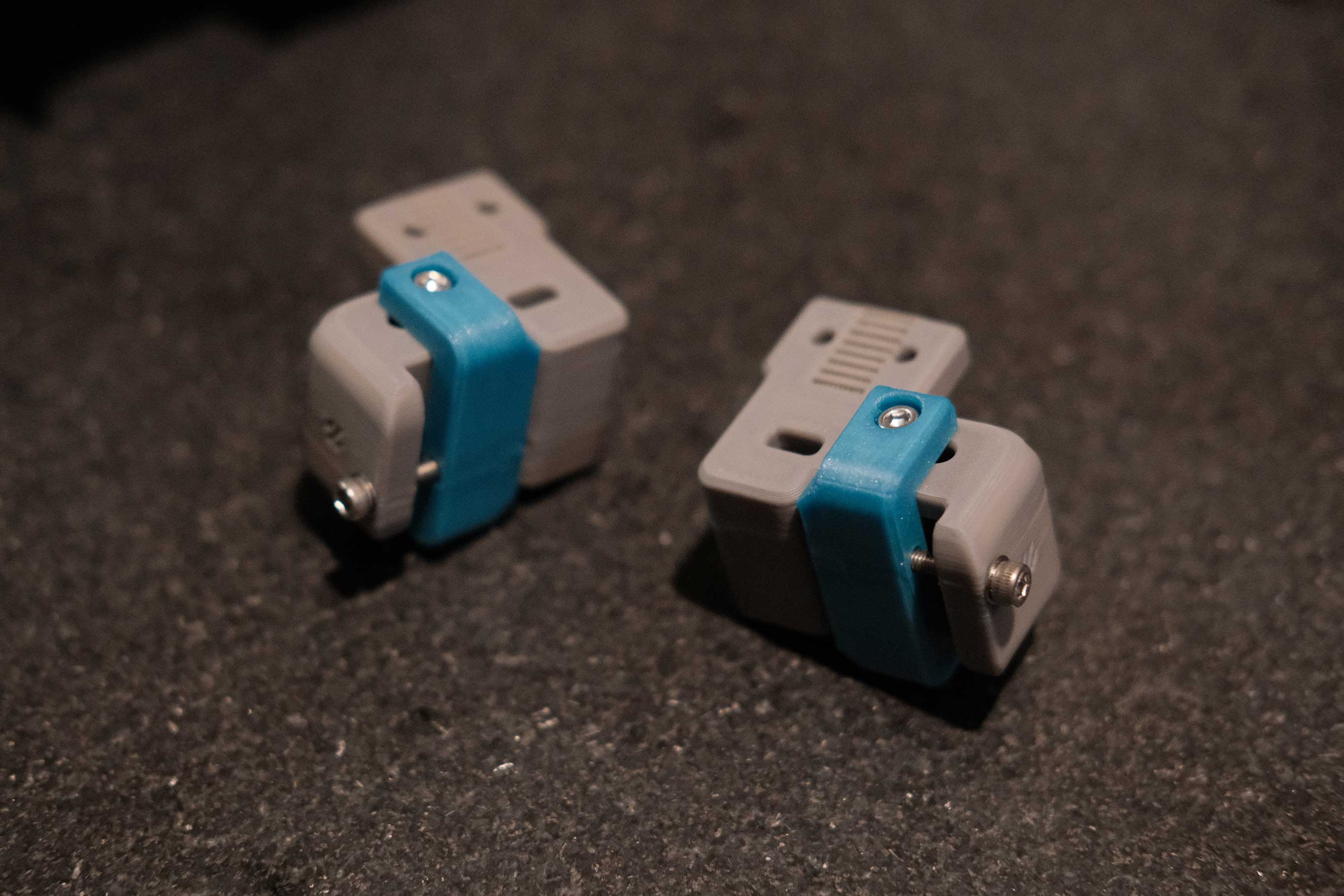
Z Drive
I created a little 3.5mm spacer to set the proper distance between the two pulleys on the shaft. Holding the bottom bearing with the M5 shims is fiddly. You will keep dropping them and picking them off the floor until these assemblies go into the printed housings. The printed wheels are very easy to mount at an angle, which will introduce drift to the belt loop. Try to keep things square, and secure the grub screws in an X pattern to keep things even.
 Z Drive - 1
 Z Drive - 2
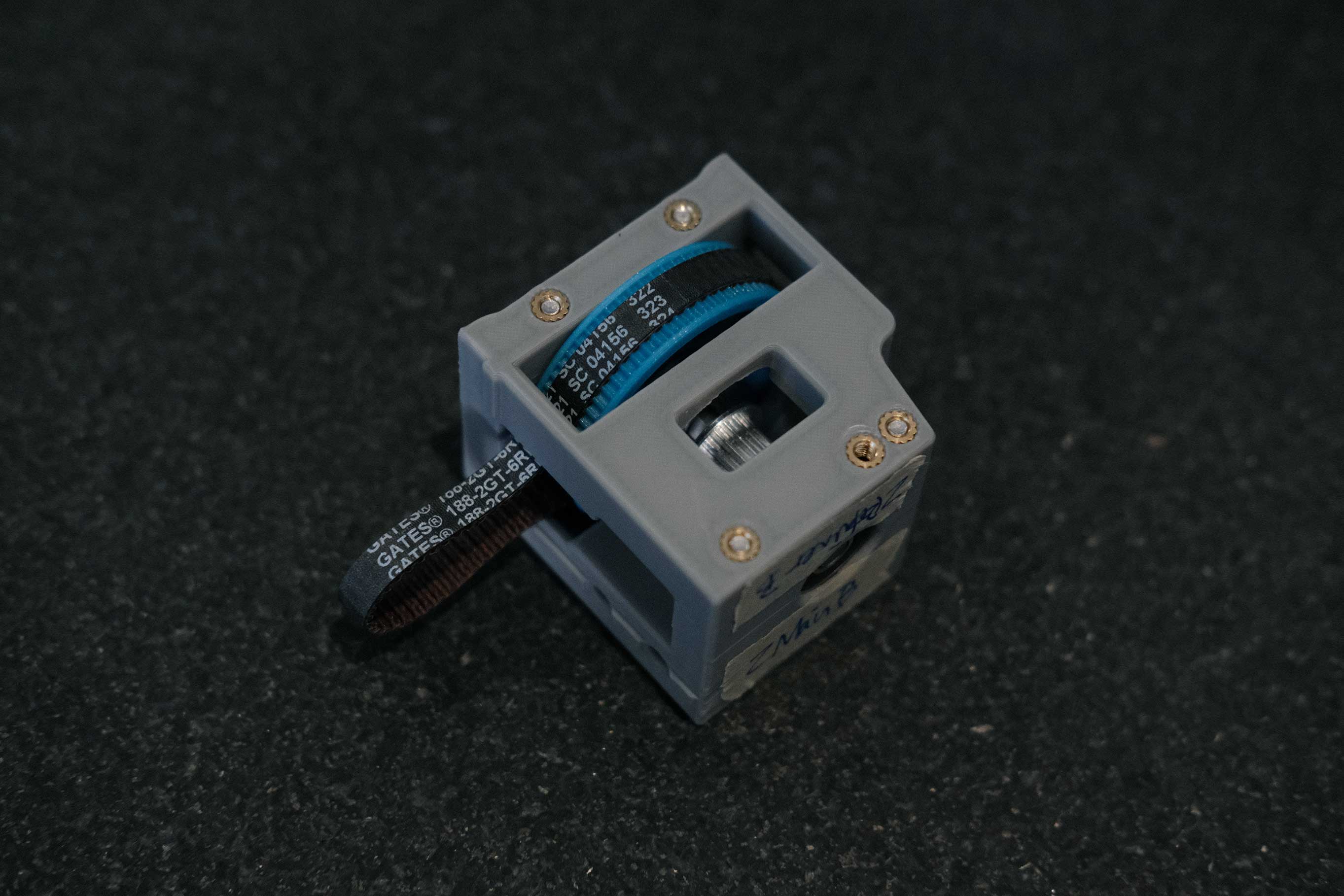
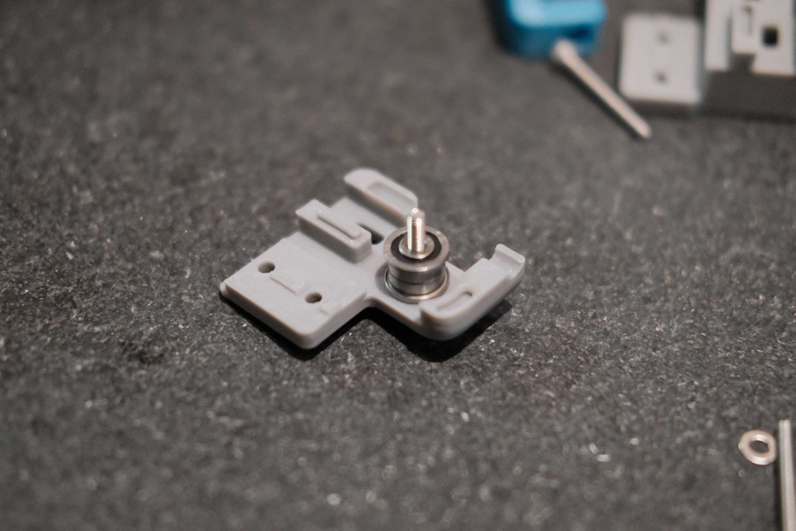
Testing the pulley assembly in the housing without the belt is a good way to see how planar the wheel’s rotation is.
 Z Drive - 3
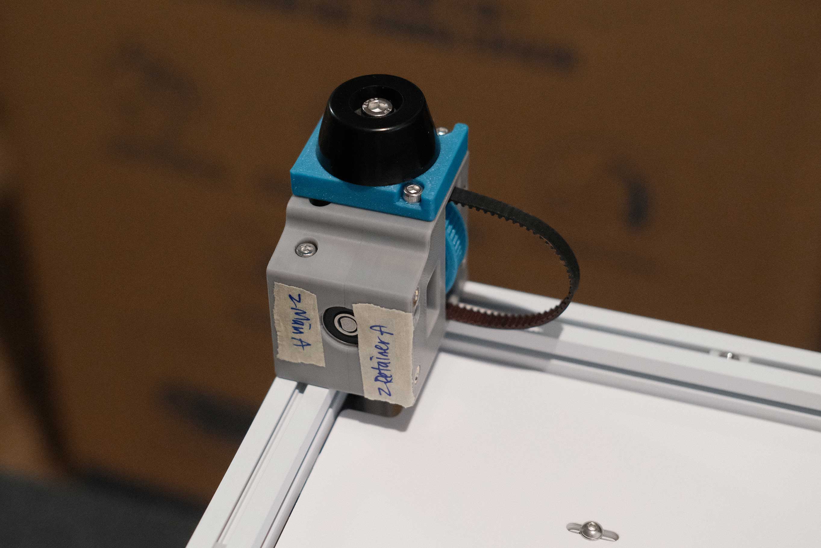
The loop should be exiting the side where the wheel protrudes. I don’t know why I pulled the belt out like this.
 Z Drive - 4
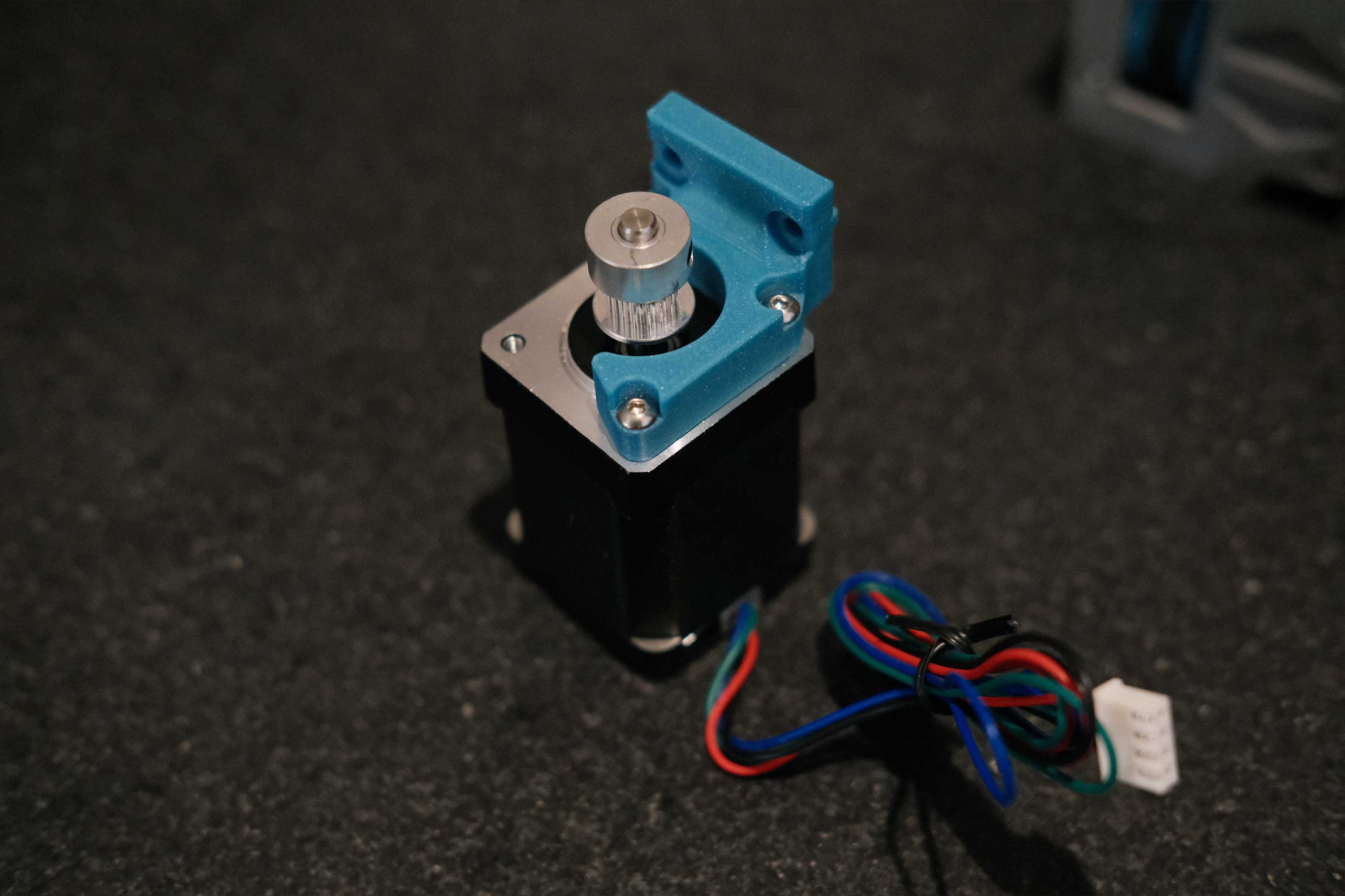
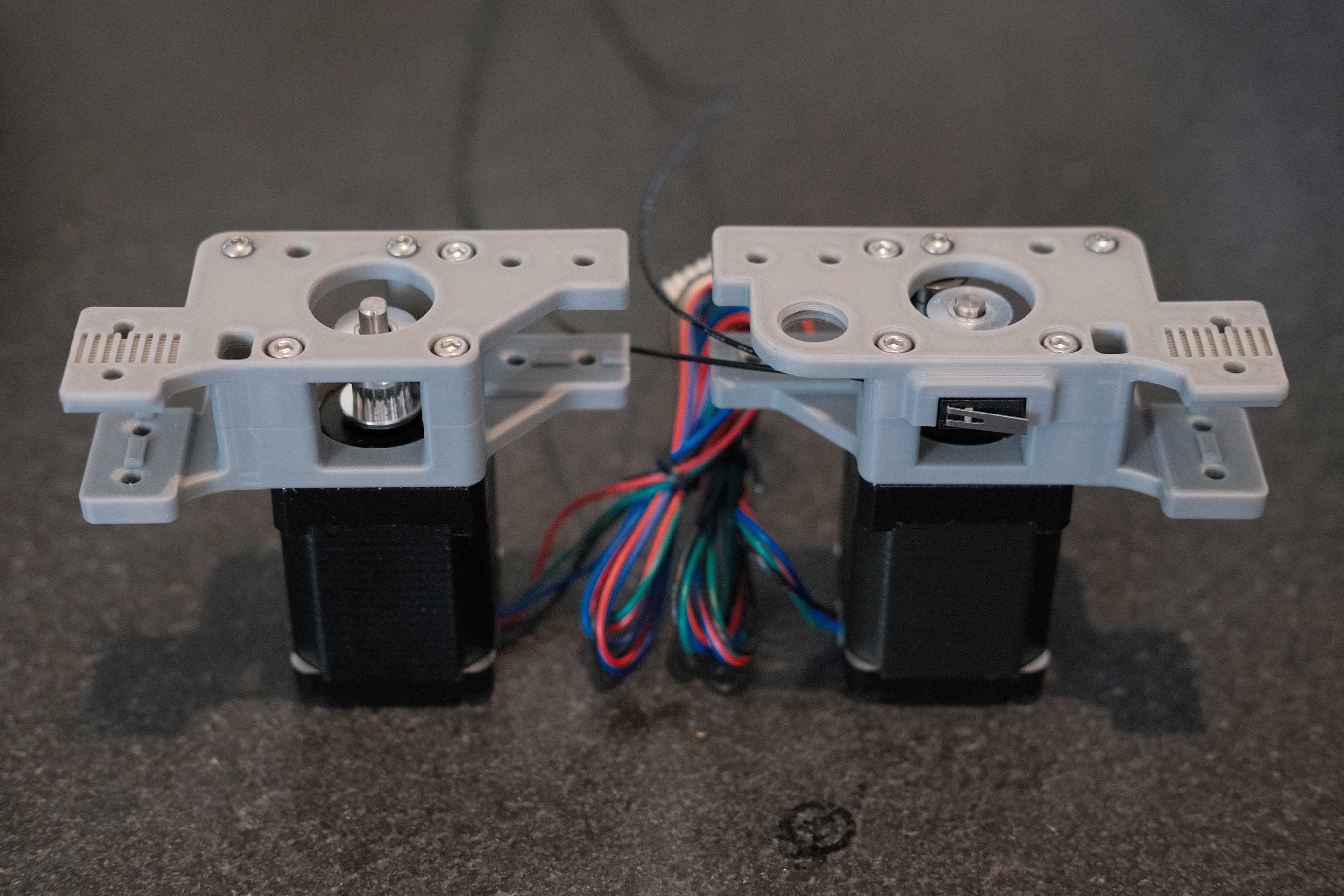
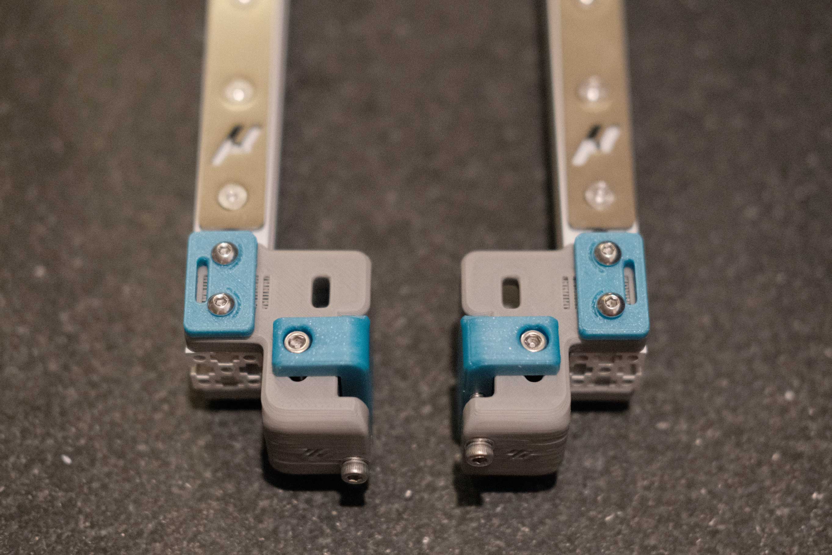
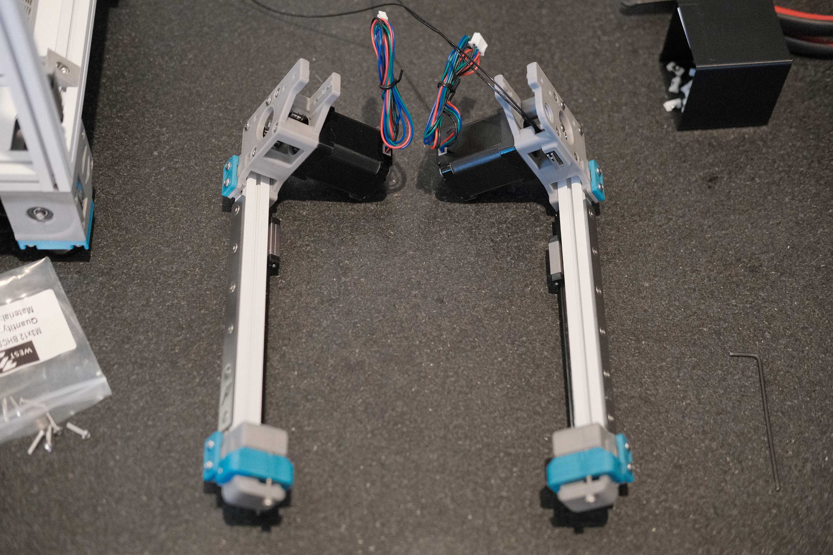
Wires face in towards the Micron’s center.
 Z Drive - 5
 Z Drive - 6
 Z Drive - 7
 Z Drive - 8
 Z Drive - 9
 Z Drive - 10
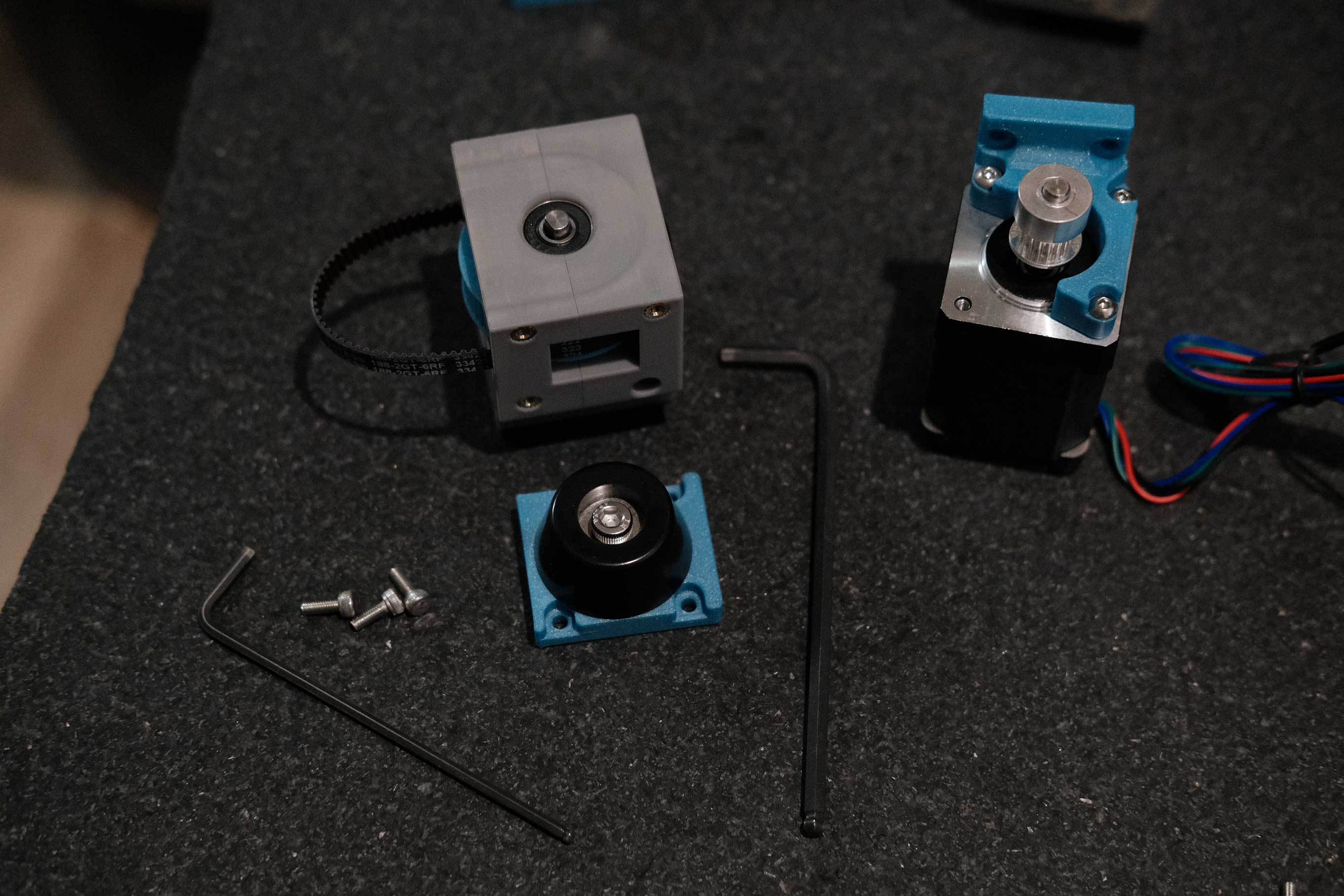
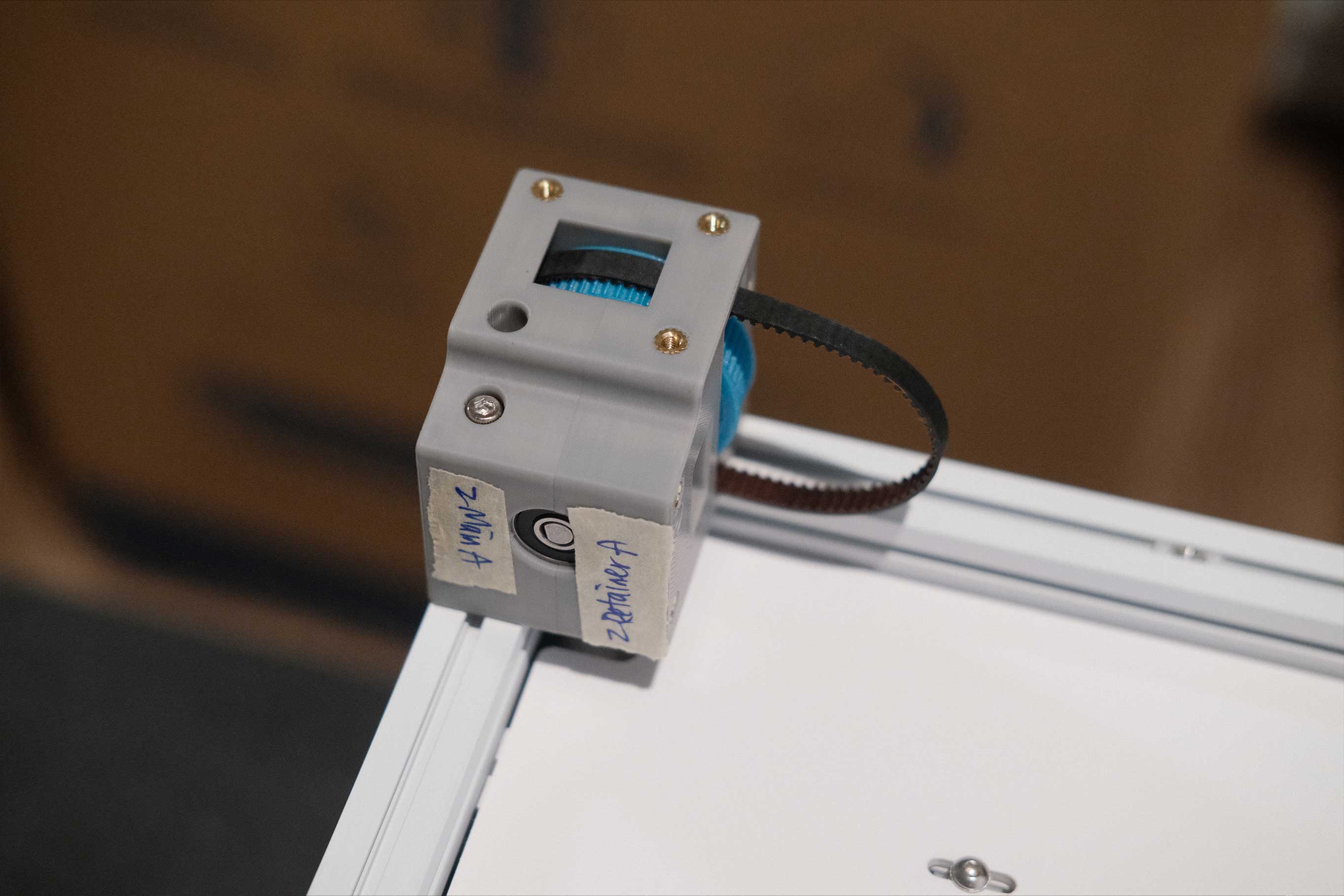
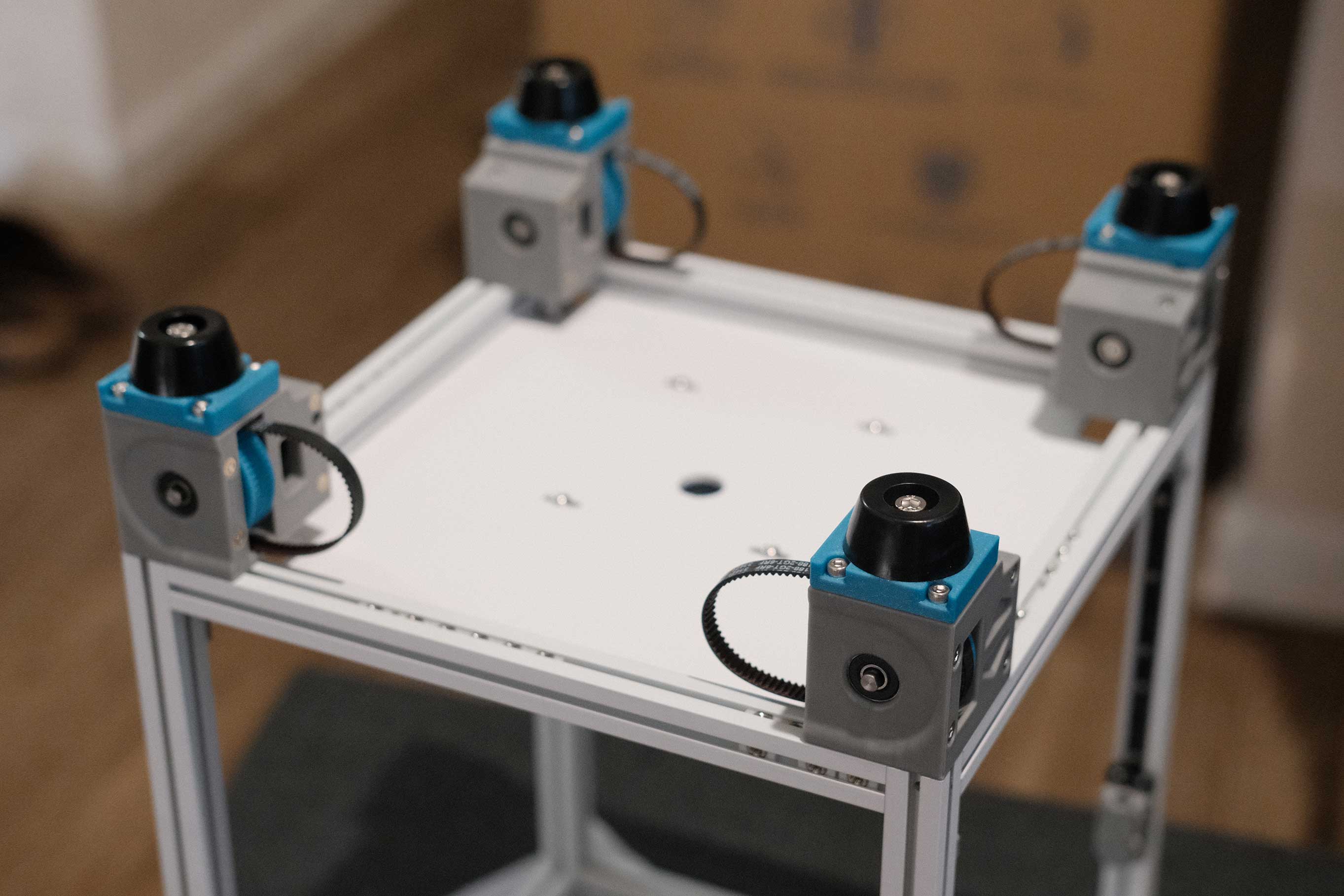
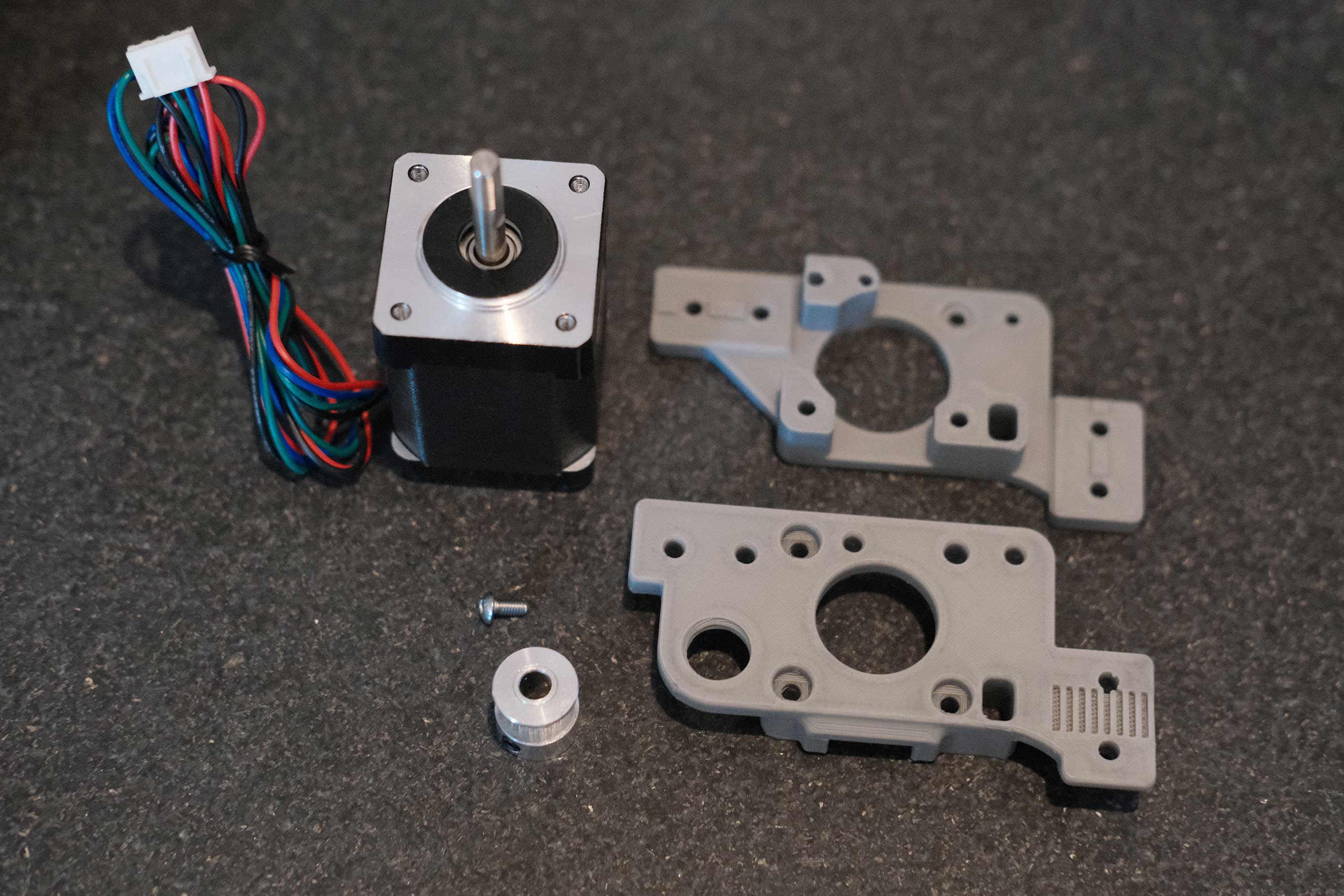
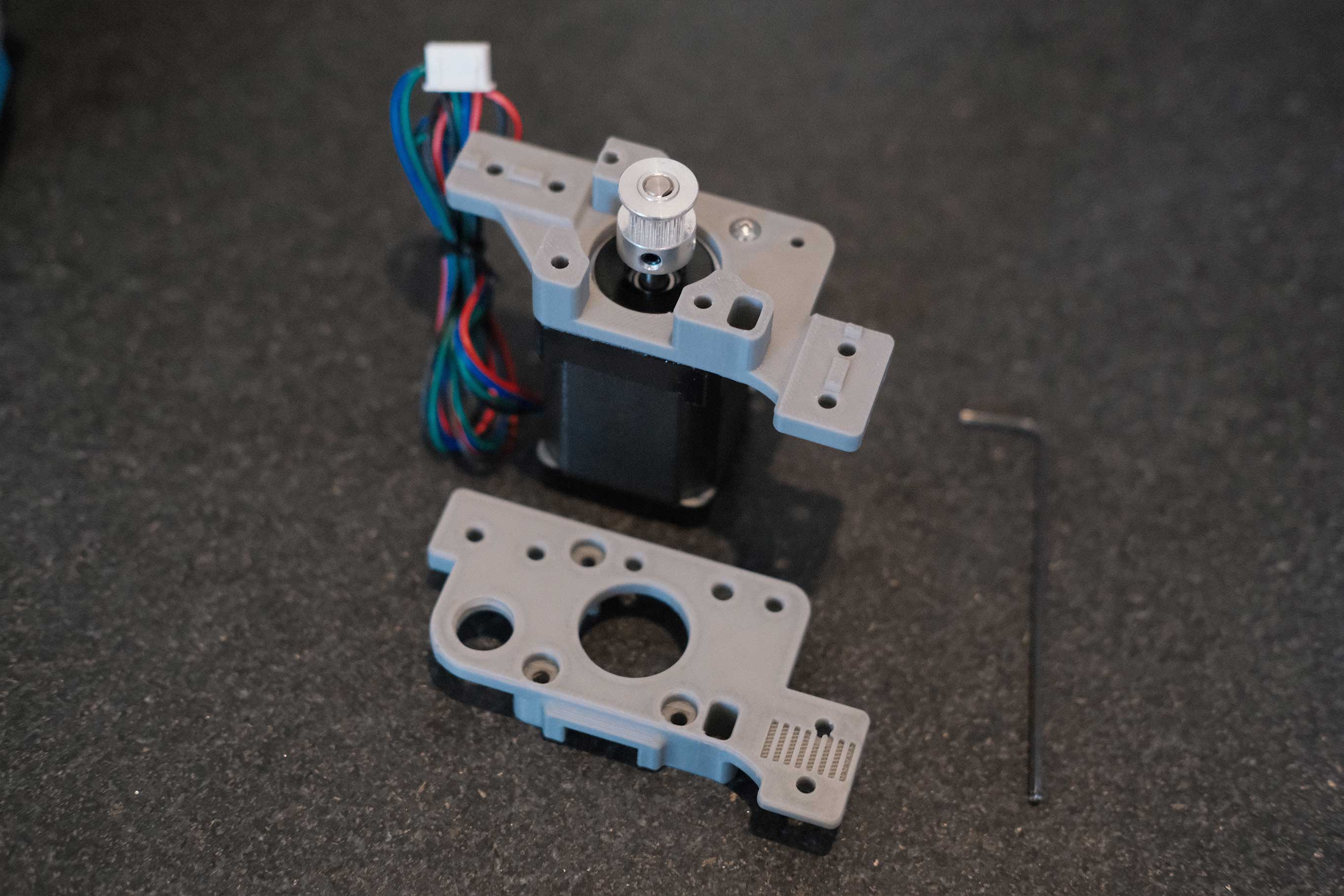
When mounting the motors to the frame, it’s important that the motor pulleys are parallel to the corner Z drive shafts. This will keep the belts centers on the pulleys. If they are canted, the belt will drift and rub against the pulley sides.
 Z Drive - 11
 Z Drive - 12
 Z Drive - 13
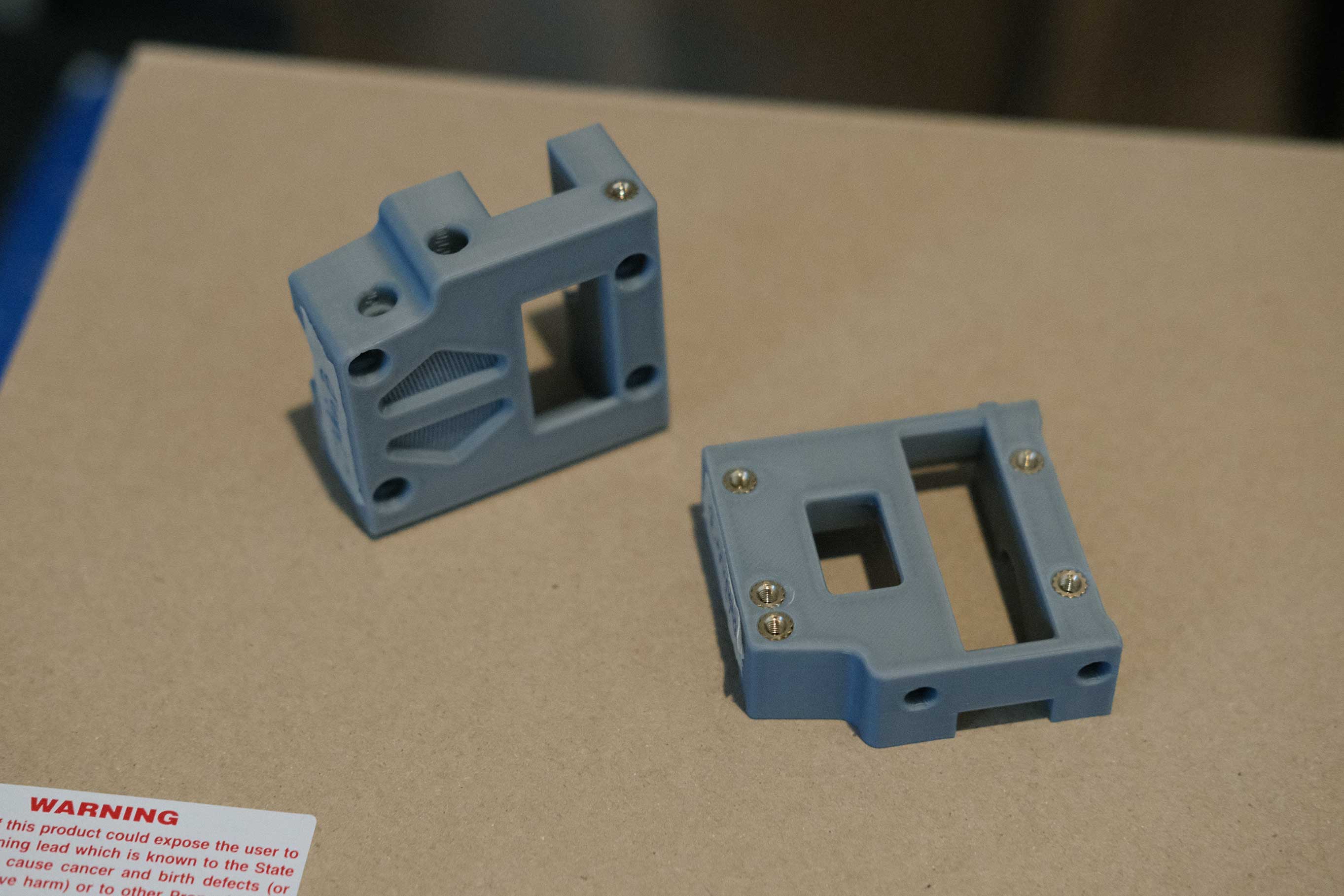
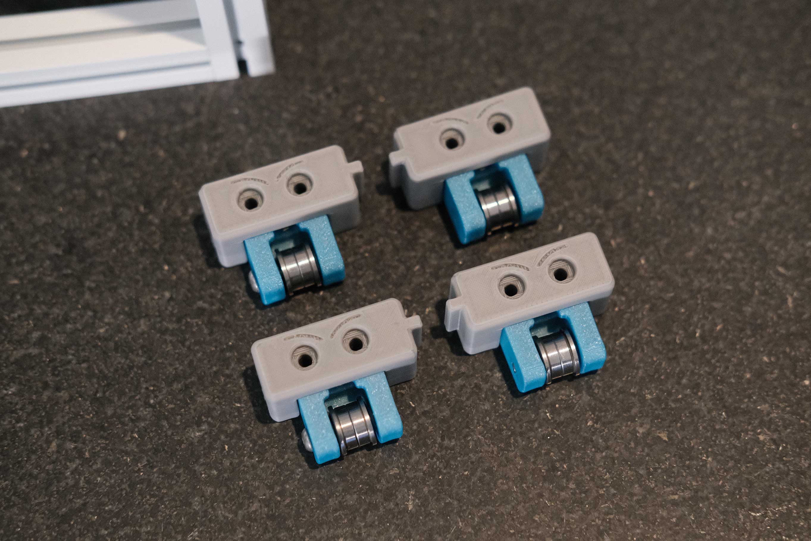
Z Idlers
According to the manual, M3x16 BHCS are used to secure the two printed parts together, but neither the DFH kit nor the West3D fasteners kit came with any. Additionally, even M3x12 BHCS poked out a bit far through the nuts. I opted to use M3x10 BHCS and they look perfect.
Update: hartk confirmed that they are intended to be M3x12 BHCS.
 Z Idlers - 1
The screws holding the bearings enters the printed part opposite the side with the frame notch.
 Z Idlers - 2
Adorable.
 Z Idlers - 3
 Z Idlers - 4
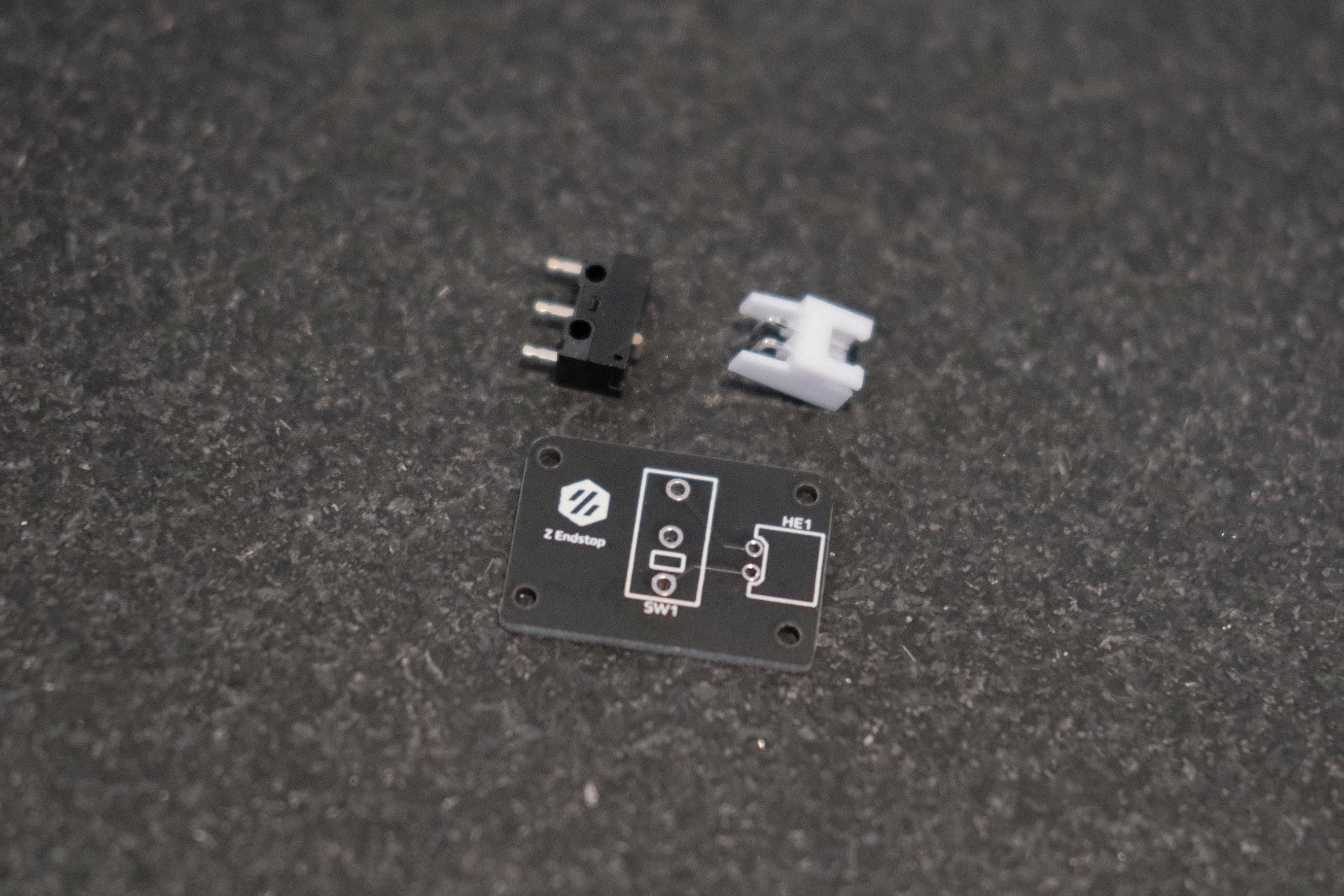
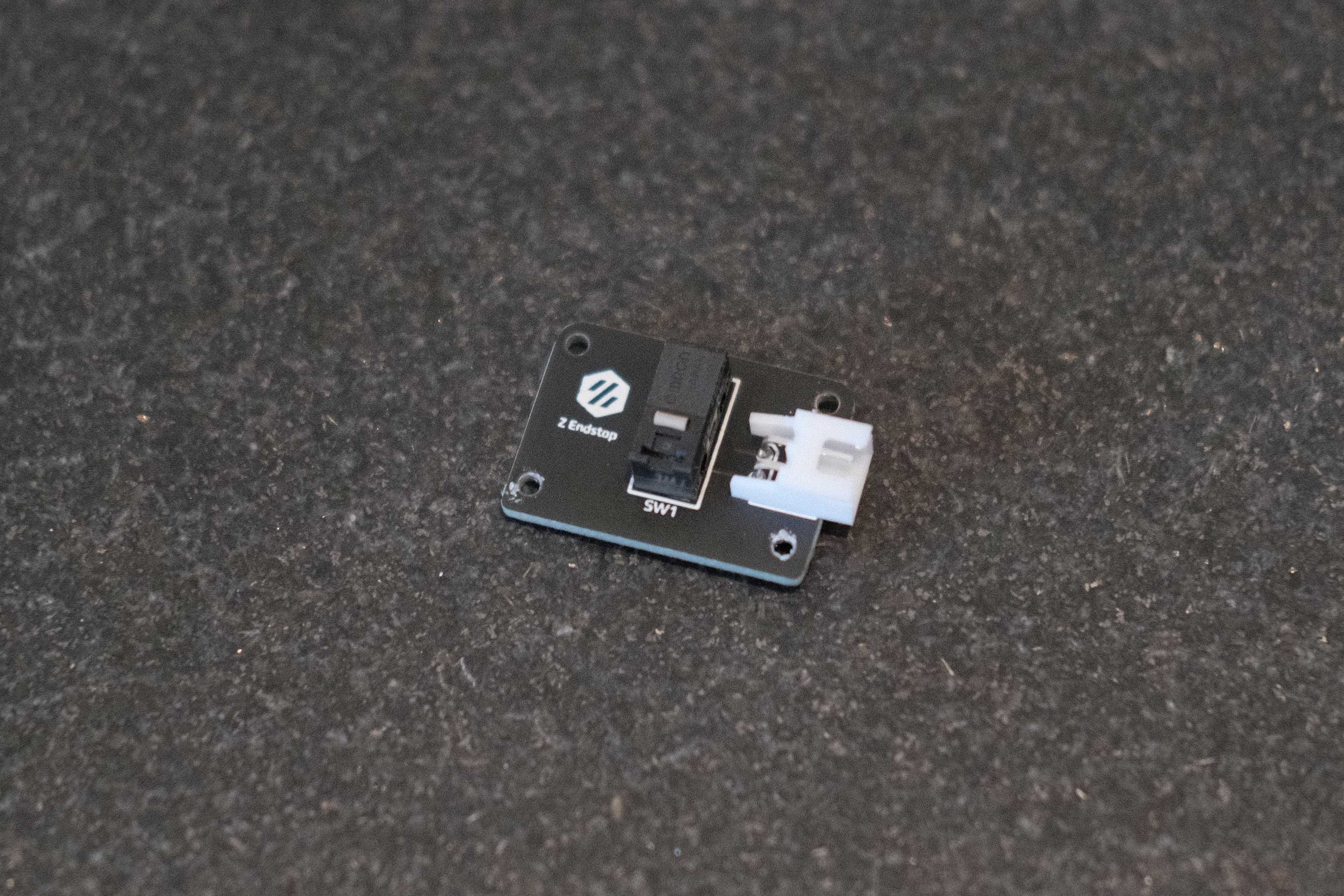
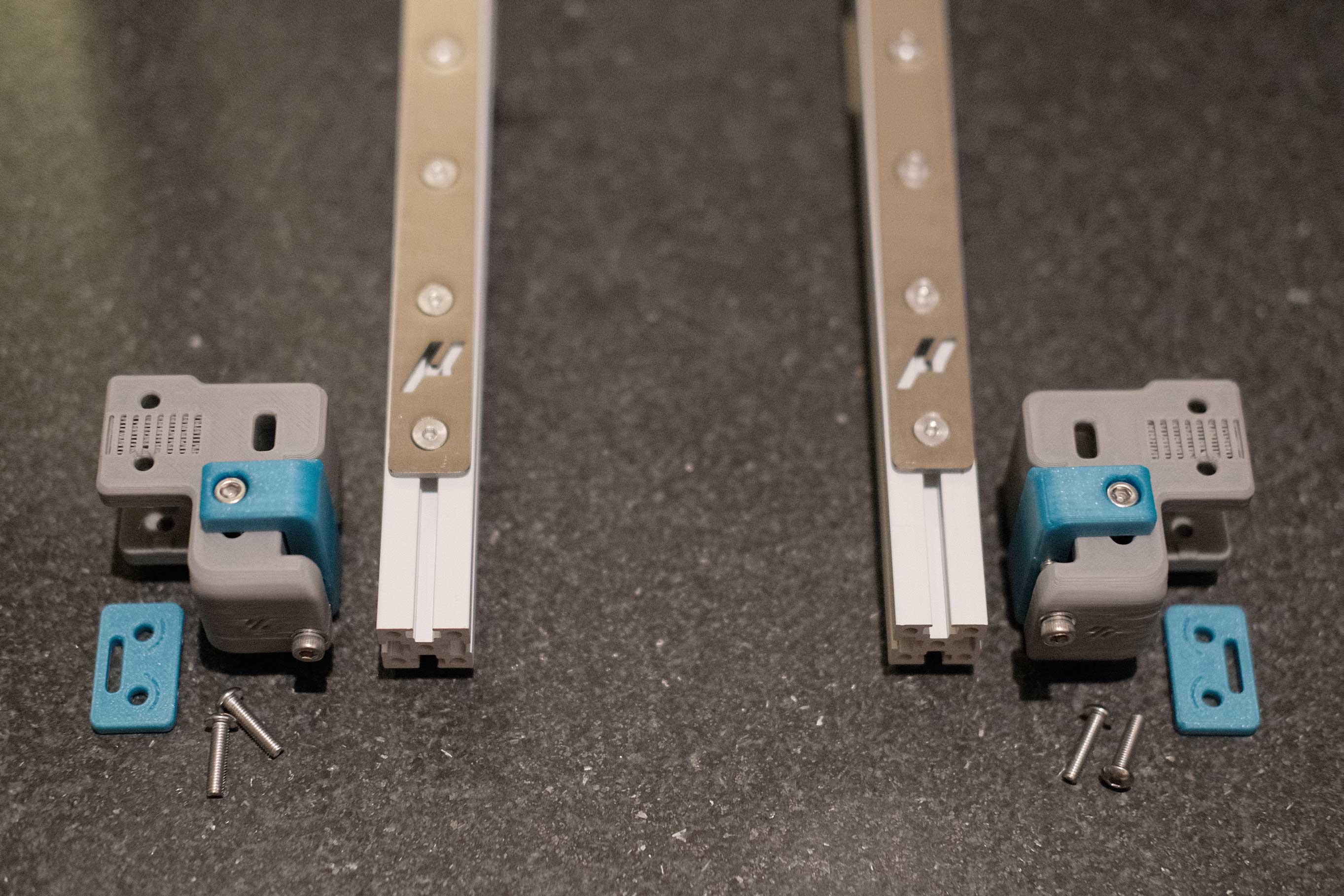
Z Endstop
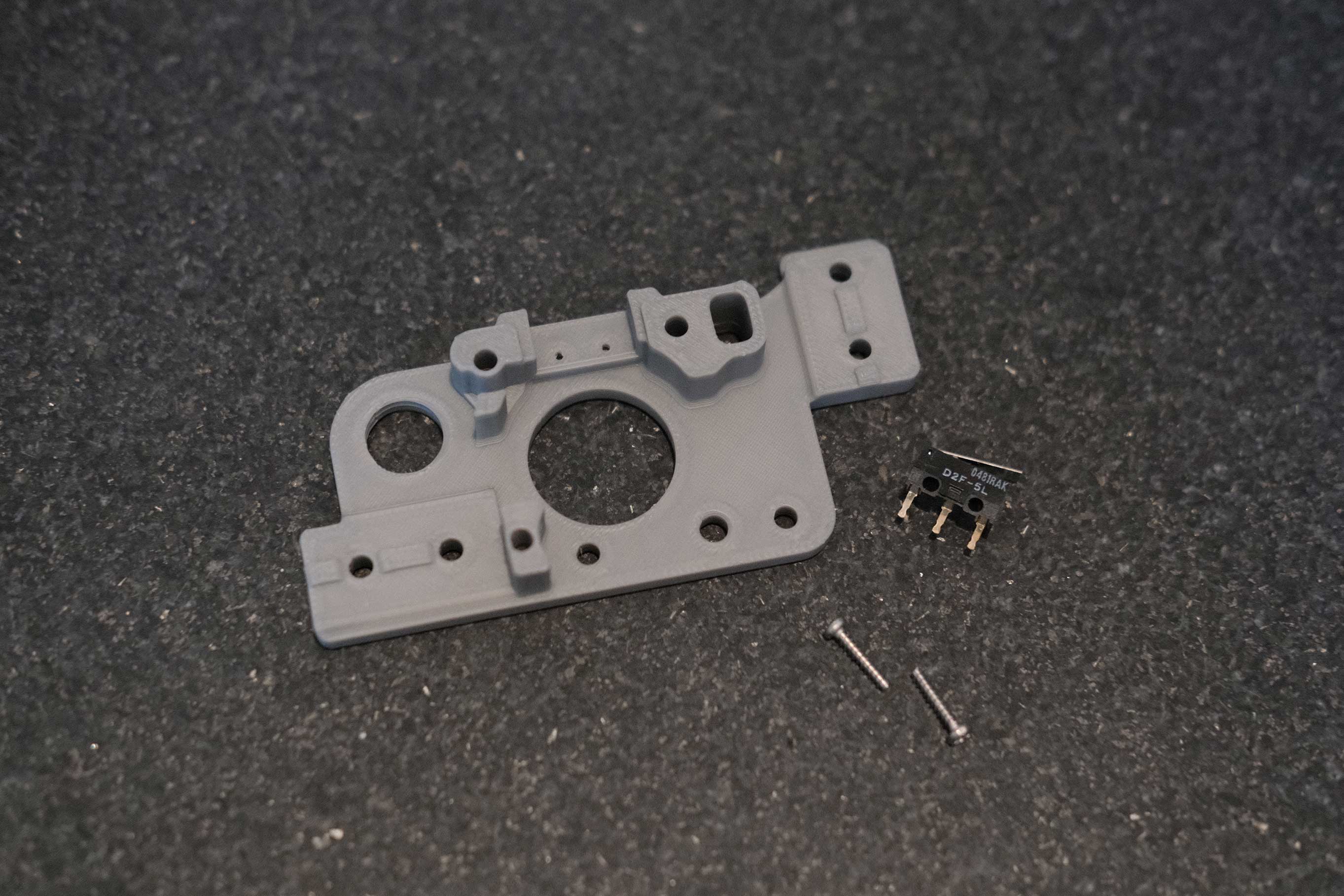
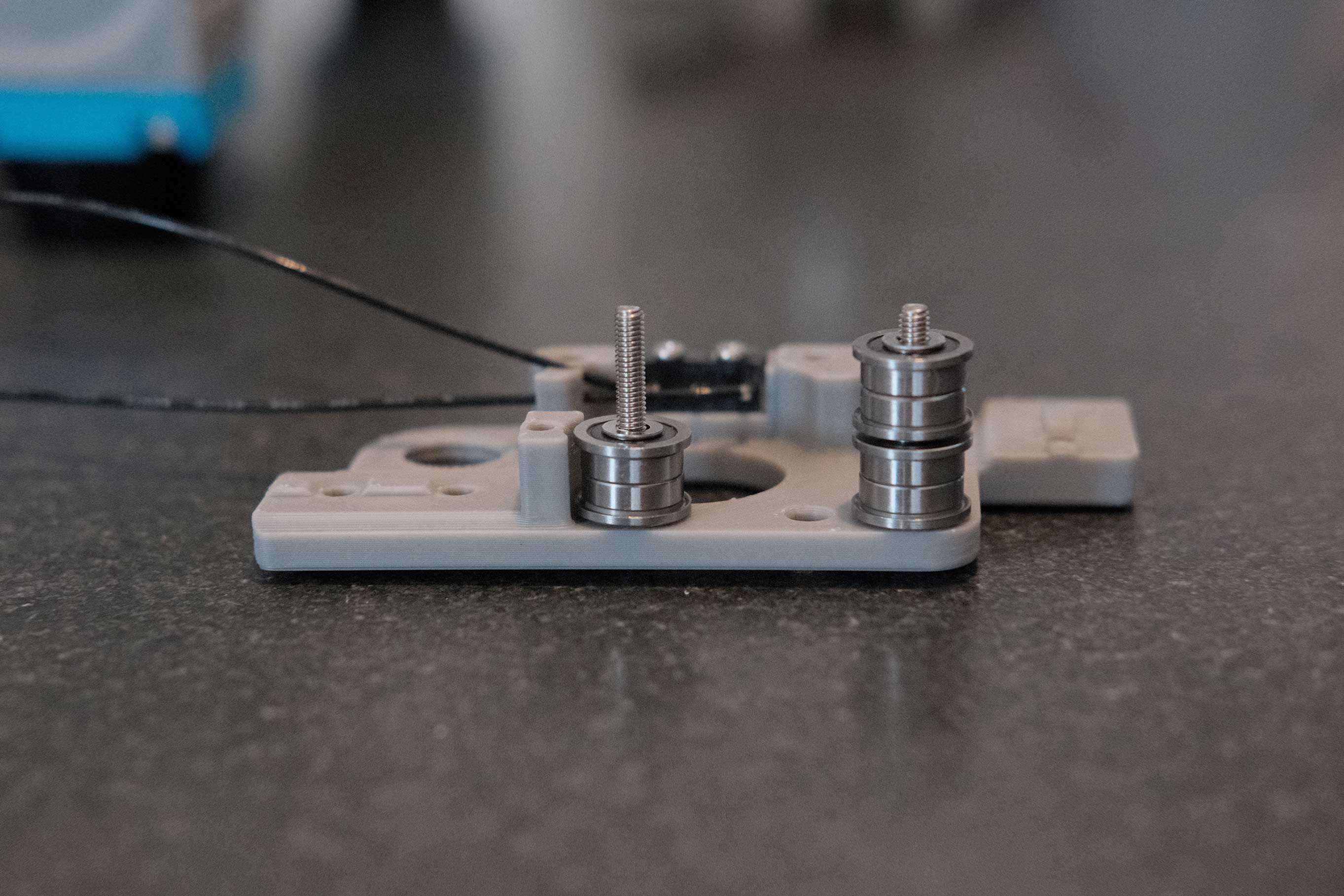
There are supposed to be four M3 shims to extend the barrel. In my case, the screw is already short, so they are not necessary. I will use a bit of low strength thread locker later to set the proper height.
Update: I am sourcing a taller M4x5x20 chicago screw. The ZeroFilter mounting brace presses against the Fabreeko edge-to-edge heater bed and prevents the mounting screws from actually mounting. To solve this, I’m using some M4 nuts on top of the knurled nuts to give some more clearance and longer mounting screws, but the M4x5x12 chicago screw is too wobbly when extended to that height.
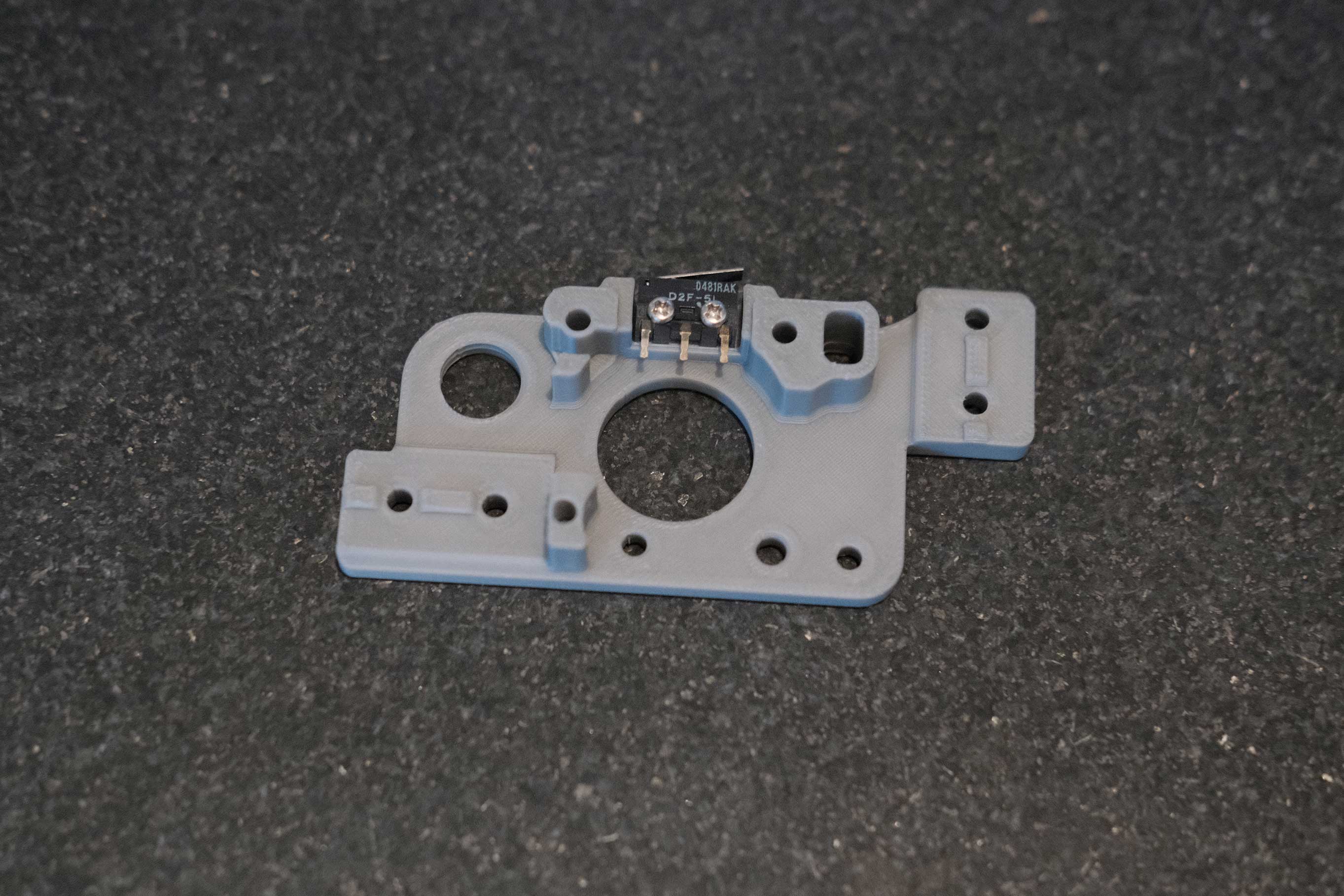
 Z Endstop - 2
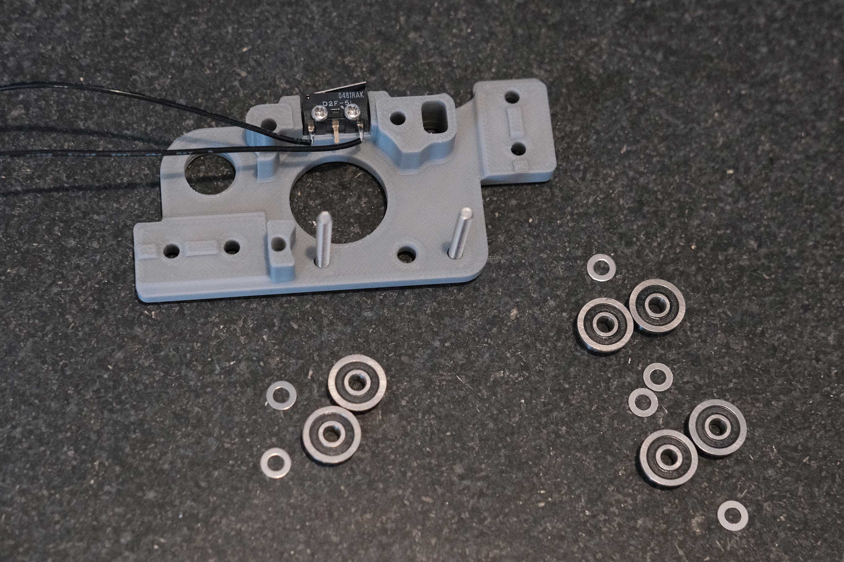
 Z Endstop - 3
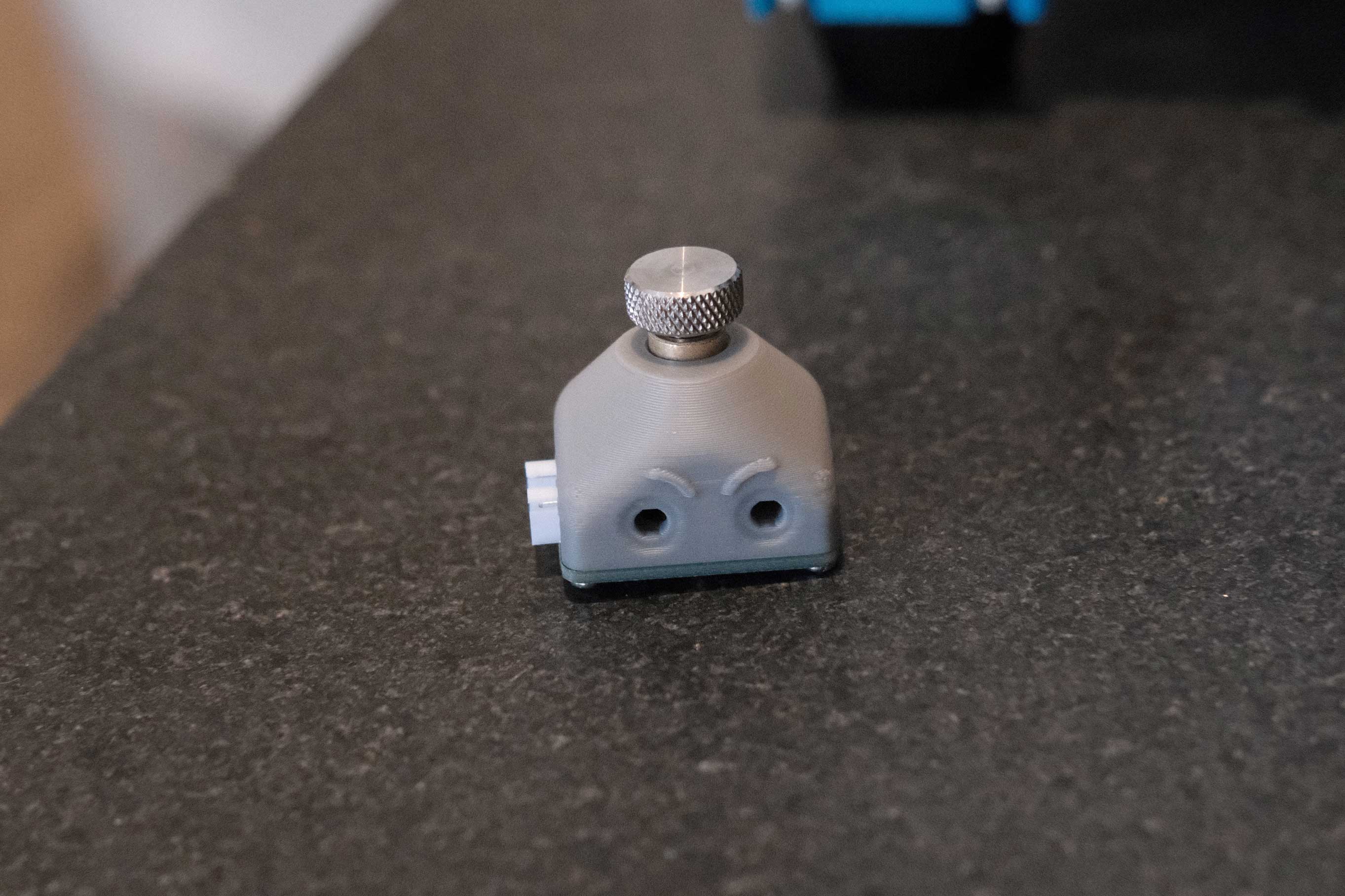 Z Endstop - 1
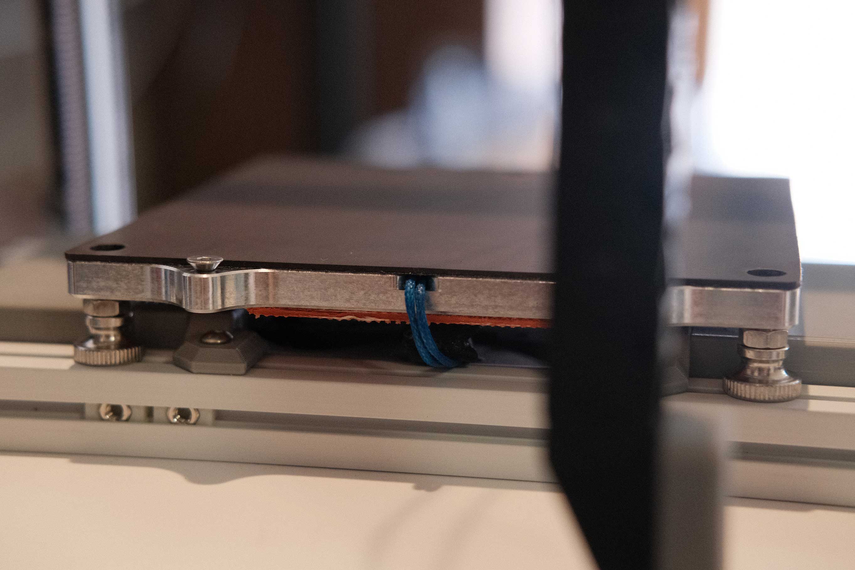
Bed
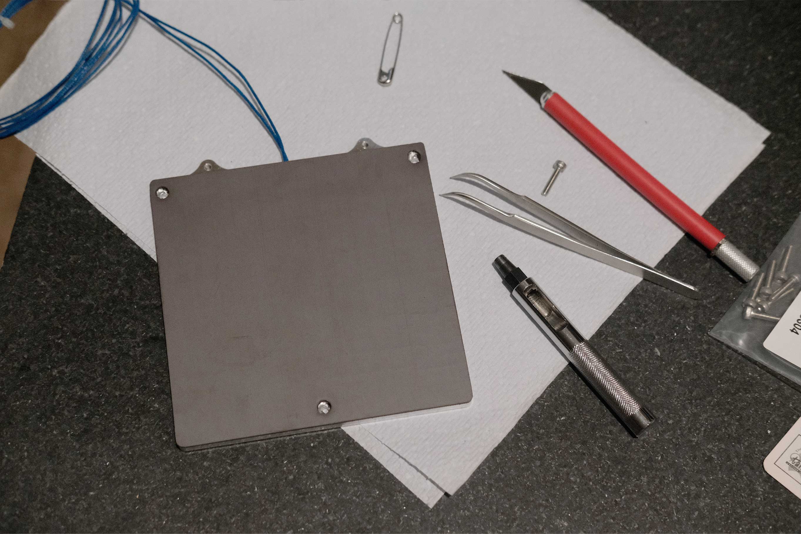
This is a bed from PrecisePrinterParts. A few of the nicer features are the thermistor slot, indexing hole for flex plate alignment, and flatness within 0.02mm.
The newest Micron design actually uses 4-point bed mounting like the v2.4. To get around this, I am using the bed mounting system from an older Micron design where the aluminum extrusions are horizontal and accommodate v0.1 beds. Plus, it works with ZeroFilters. Alternatively, you could use the included printable drill guides to make it 4-point mounting, without ZeroFilters.
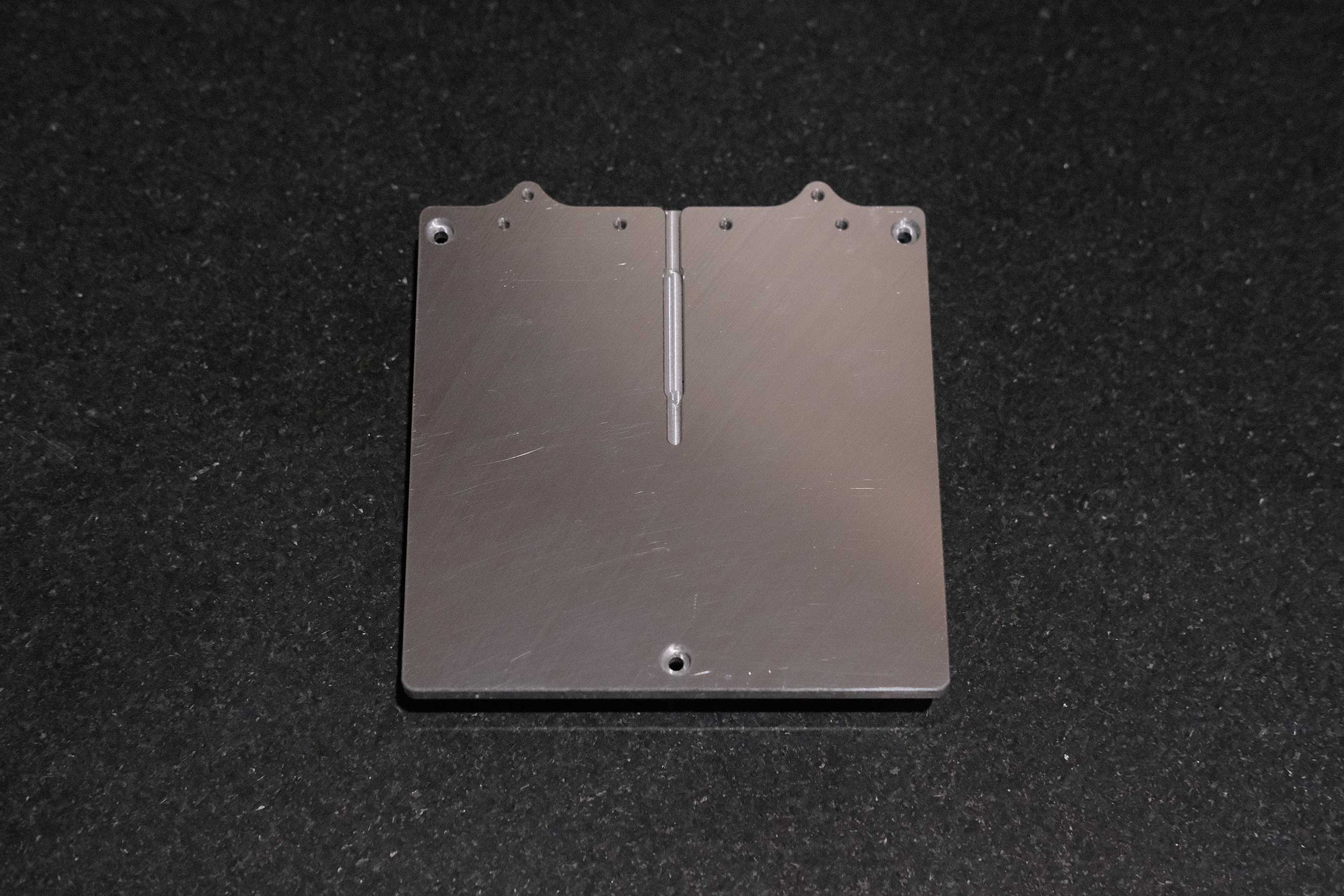 Bed - 1
To keep the thermistor from sliding back out, I added a dab of super glue. The datasheet says it should be able to withstand up to 275°F, so it should hold for awhile.
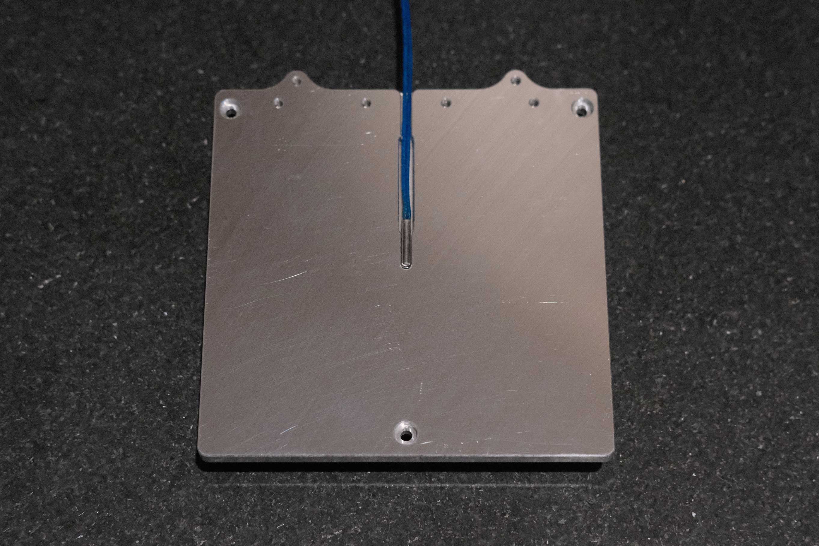 Bed - 2
Installing the Graviflex magnetic sheet just like how Nero does it. Peel back a small section to align to one edge. Tack the adhesive down with even pressure from the center towards the sides. Peel back a bit more and tack it down. Repeat until covered and trim the excess.
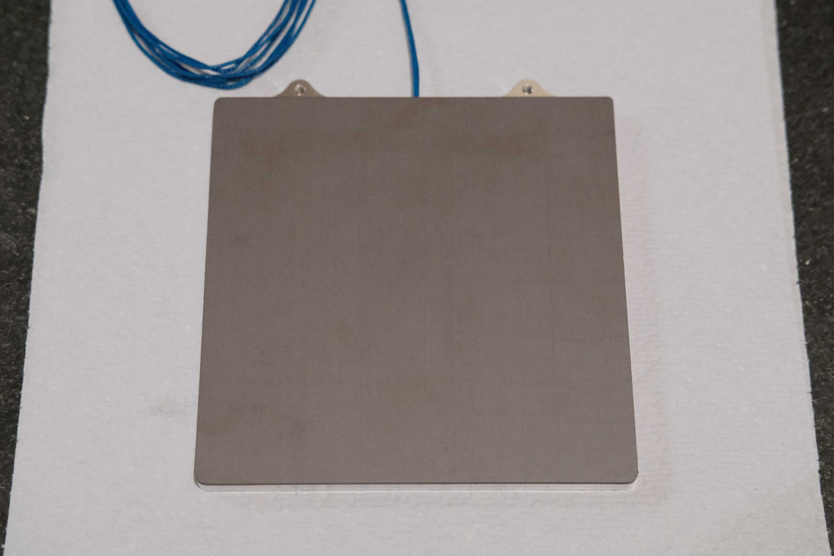 Bed - 3
The safety pin is to poke a hole through the Graviflex for locating on the top side. Cutting the screw holes in the Graviflex sheet was actually pretty hard. The adhesive has a lot more stretch than the standard stuff and the leather punches I use for clean holes didn’t cut it (literally). I used an exactly knife to remove some, and used a suitable sized leather punch to force the remaining edge material down into the countersunk holes.
 Bed - 4
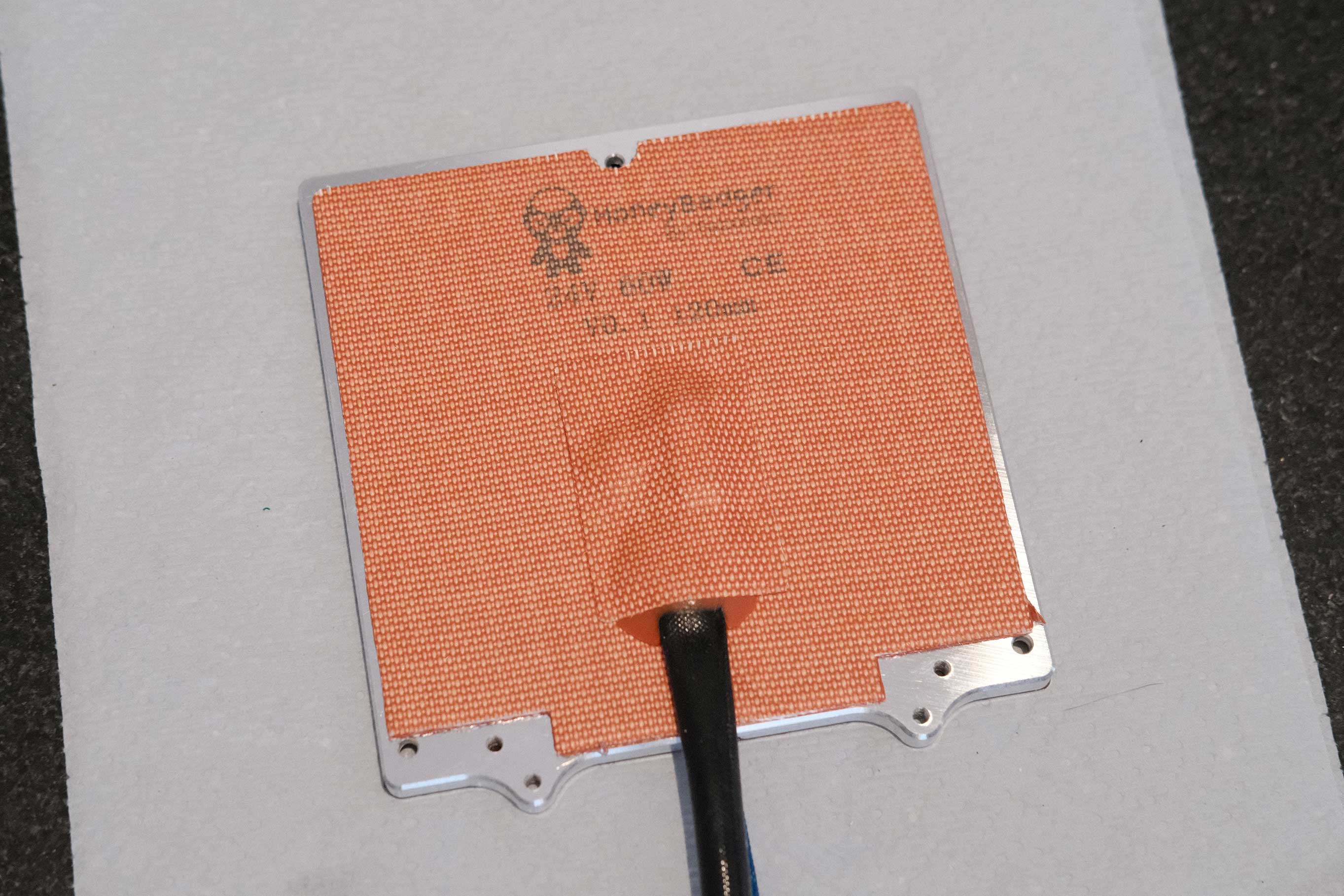
Fabreek’s edge-to-edge heater. I had to trim just the tiniest bit around the 3 mounting holes to make space for the knurled nut standoffs (not shown in the photo). I DO NOT RECOMMEND DOING THIS.
 Bed - 5
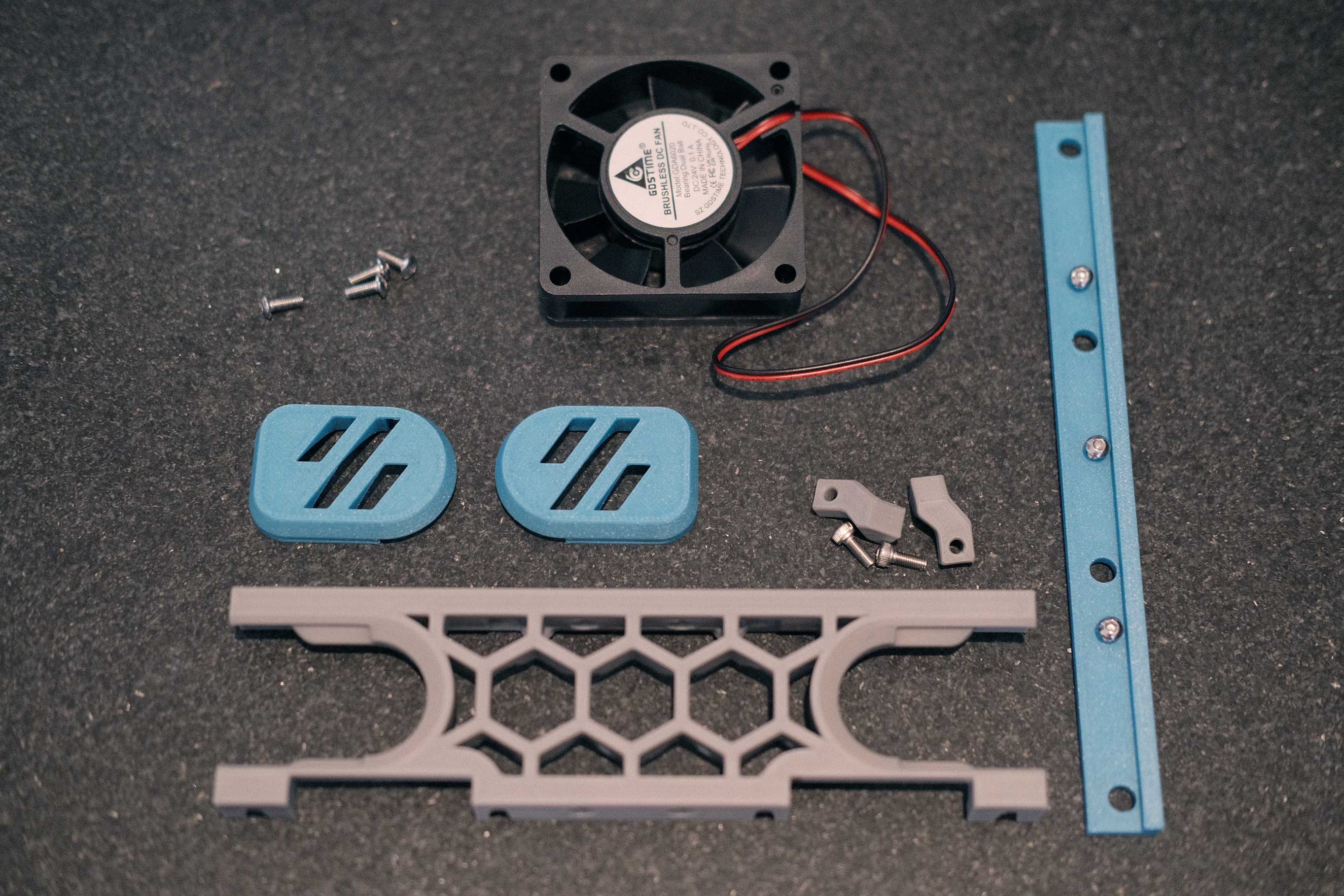
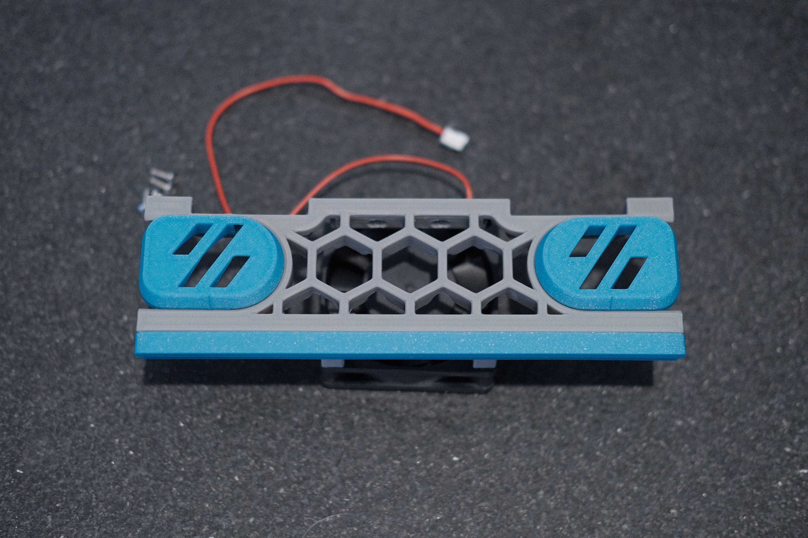
ZeroFilter
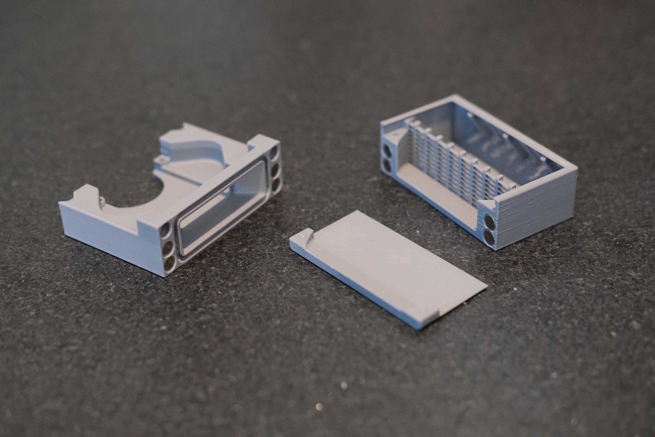
 ZeroFilter - 1
 ZeroFilter - 2
 ZeroFilter - 3
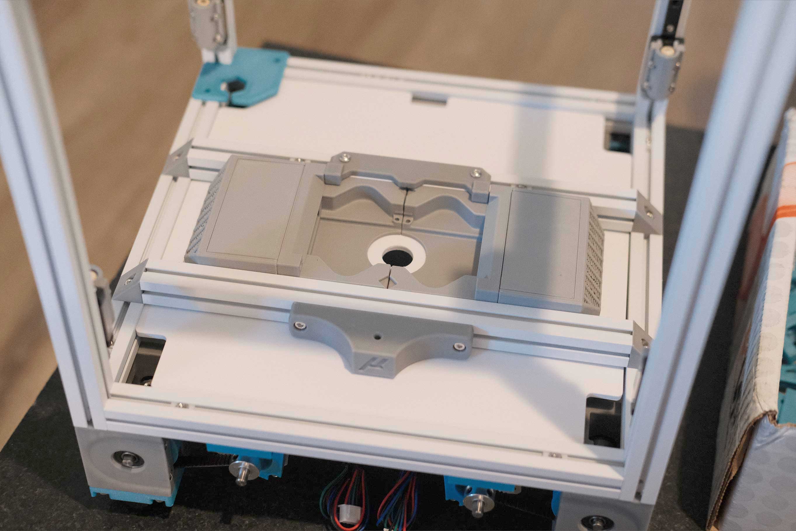
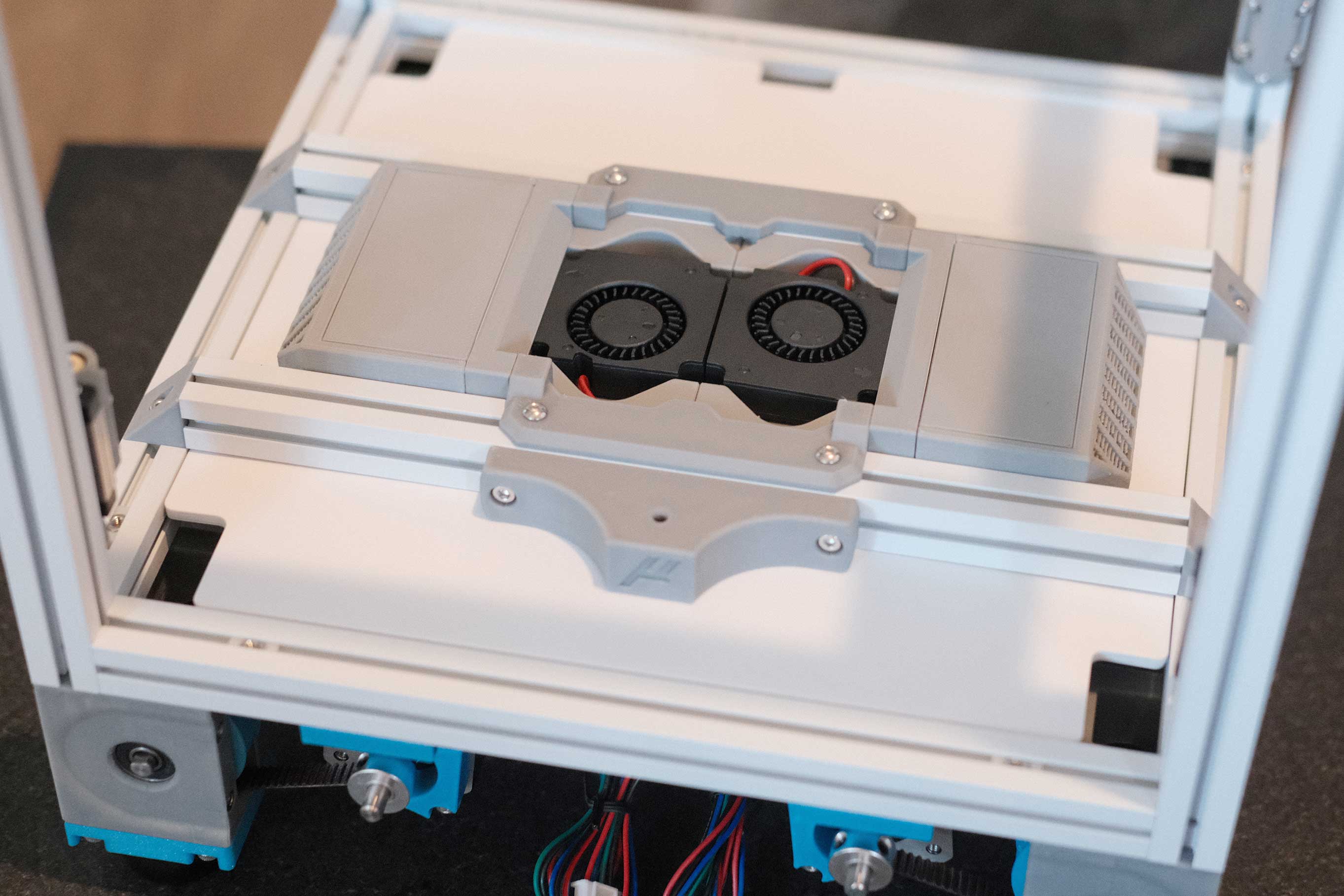
Here is where I ran into a couple of issues. The original deck’s center hole was not centered to the ZeroFilter, and moving the horizontal extrusions to make room for the parts pushes out the front mount for the bed a bit too far. I adjusted and reprinted both the deck panel and the front mount, and I added another brace to the front of the ZeroFilters to keep it all square and tight.
 ZeroFilter - 4
 ZeroFilter - 5
Y Axis
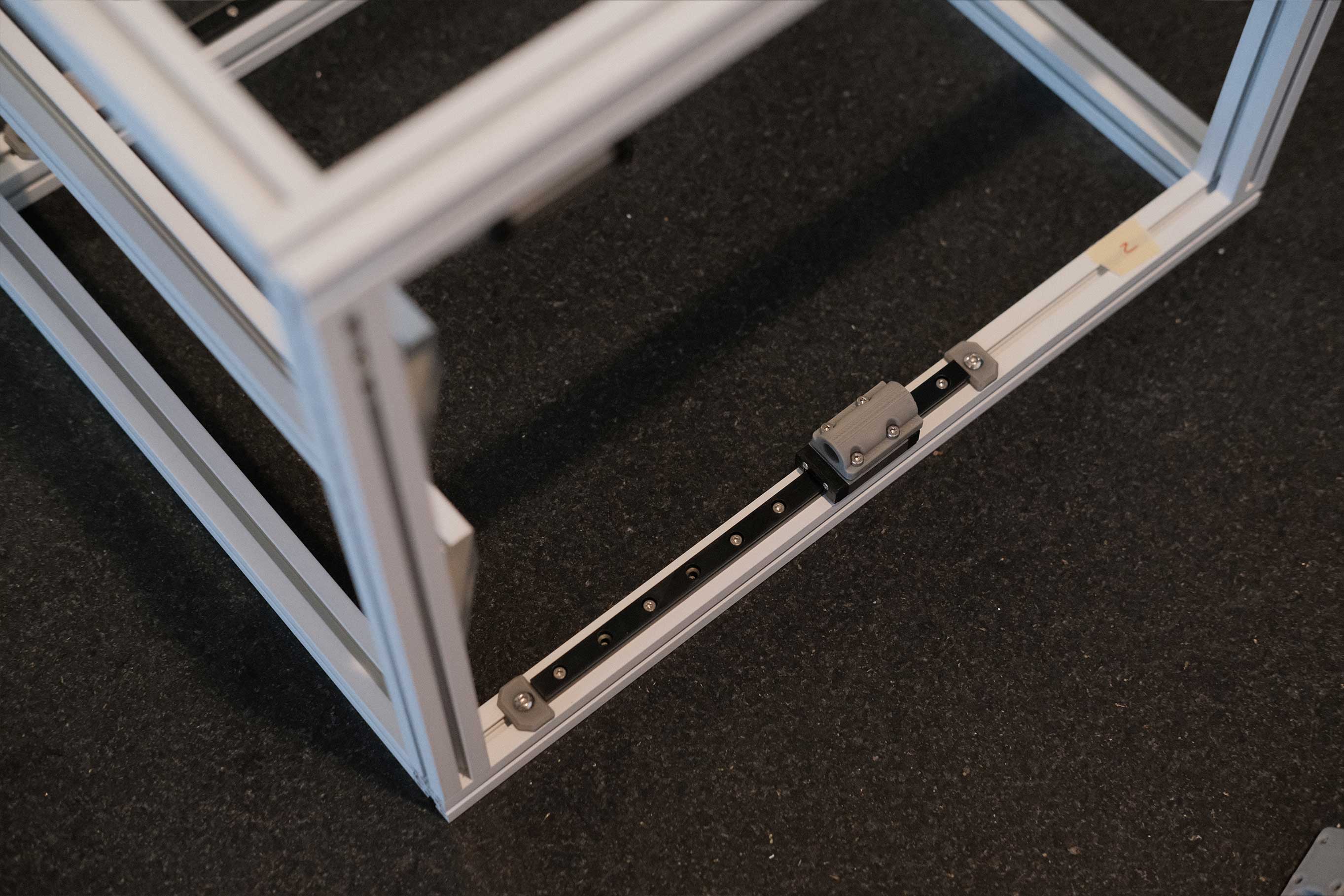
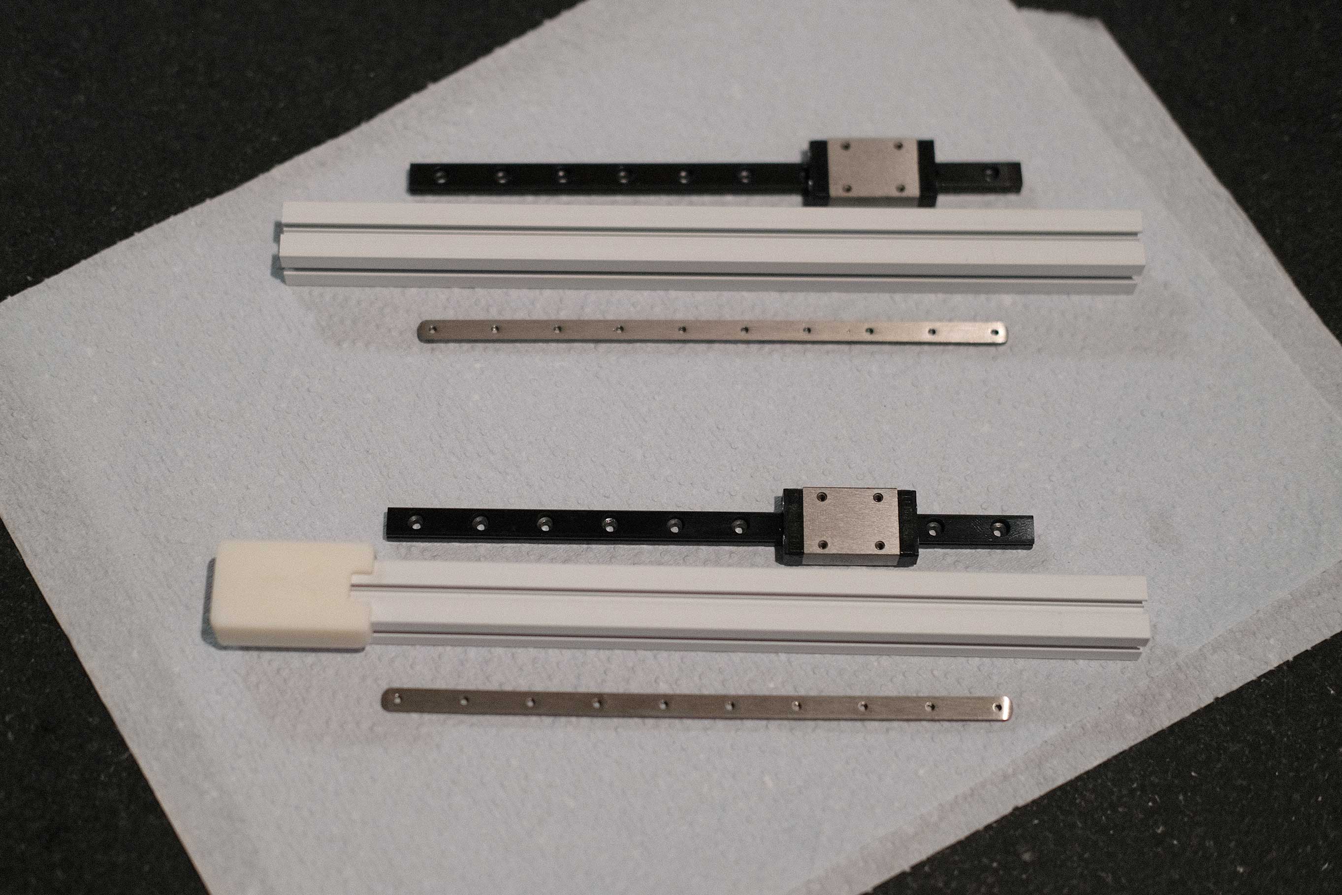
There is a printed jig for setting the distance of the linear rails from the ends, but I found that with it’s curved inner corners, it was not accurate enough for me. I had to go back with calipers to nail the centering. The other jig from the Z rails is also useful here.
 Y Axis - 1
 Y Axis - 2
 Y Axis - 3
 Y Axis - 4
 Y Axis - 5
X Axis
No fancy nut bars for the X axis. Just floating M3 nuts.
 X Axis - 1
Since there are a total of 8 holes for mounting, I did pairs with a blank in between.
 X Axis - 2
Trying to really center the rail in both directions.
 X Axis - 3
 X Axis - 4
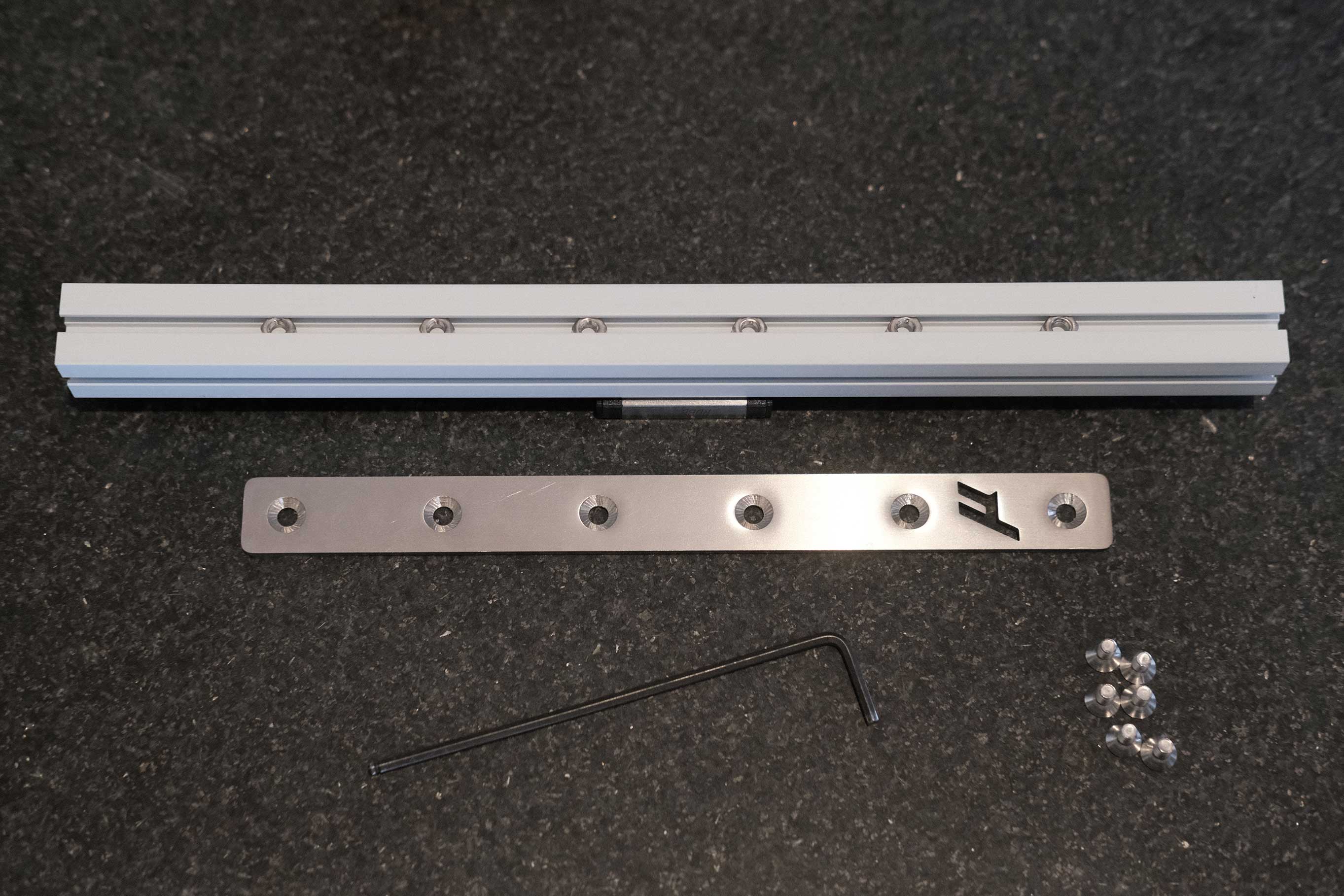
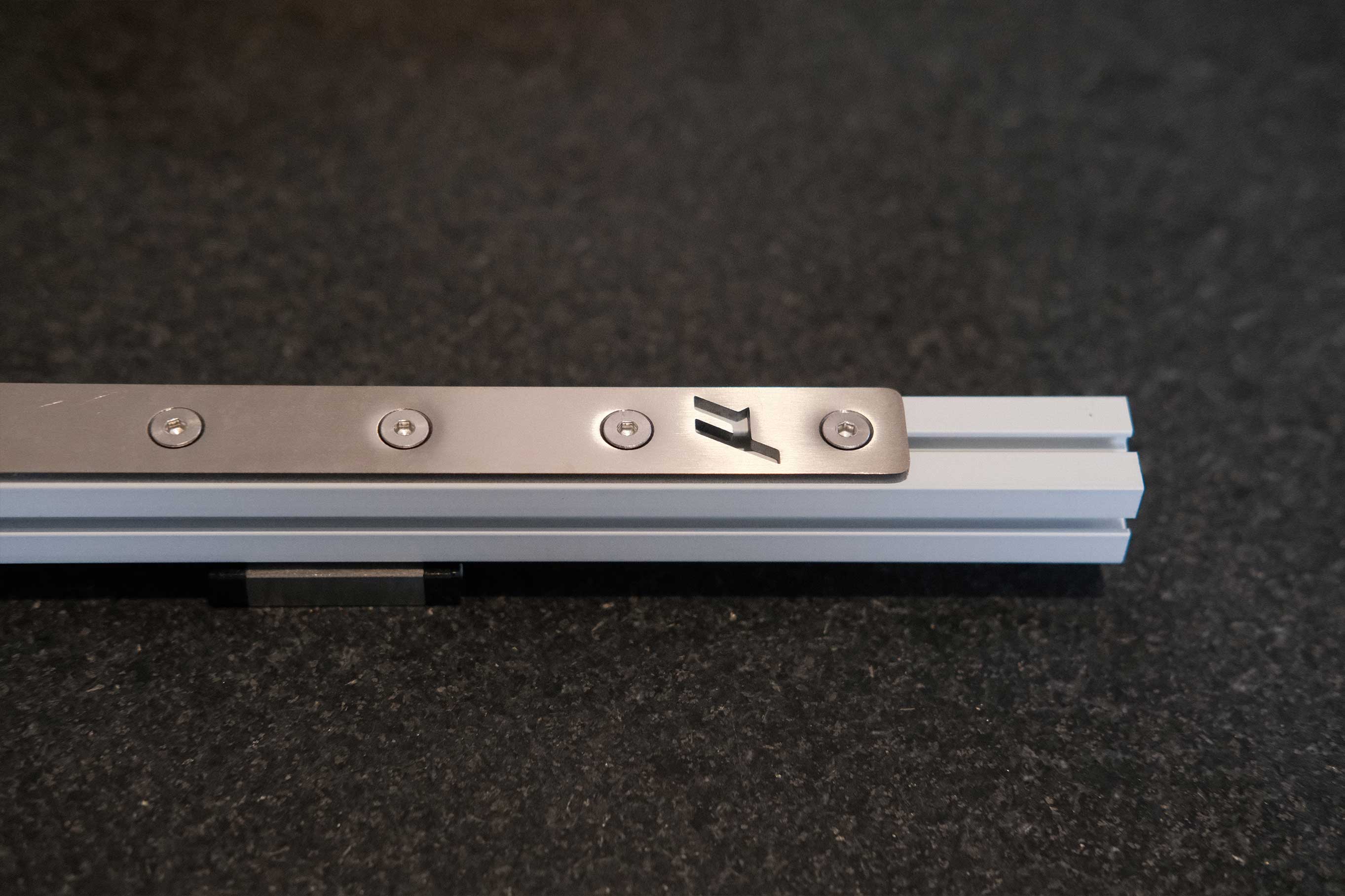
Install the titanium backers on the X axis.
 X Axis - 5
 X Axis - 6
A/B Idlers
If you look at the shims closely, you can see that they are punched out of a sheet and one side is smoother and the edges don’t catch. This is the side I prefer to place against the bearings. The rougher side will face plastic.
 A/B Idlers - 1
 A/B Idlers - 2
 A/B Idlers - 3
Its easy to get the parts confused. You’ll know you did it right if the SHCS heads on the tensioners (the accent parts) are on top.
 A/B Idlers - 4
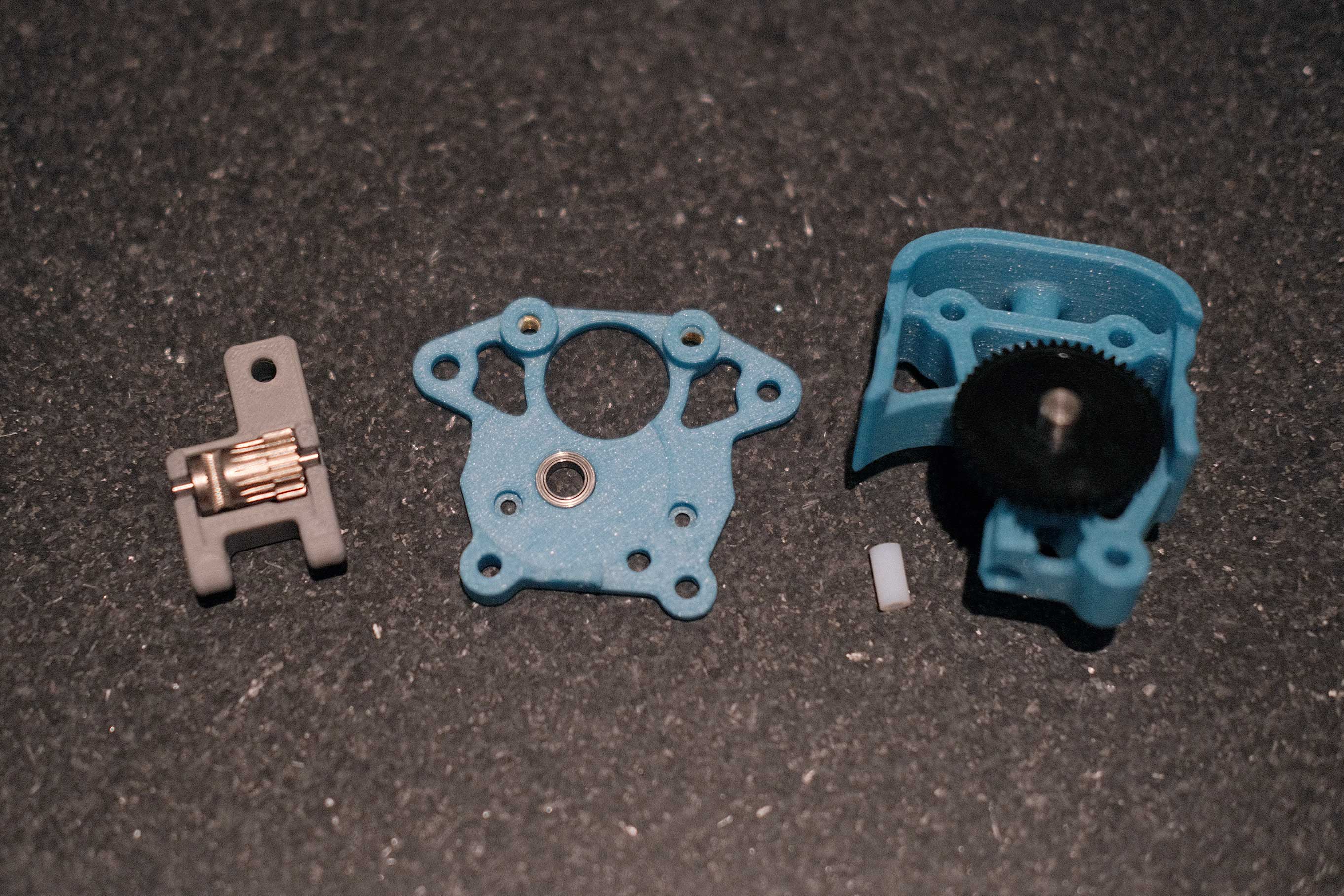
A/B Drives
 A Drive - 1
 A Drive - 2
 A Drive Top - 1
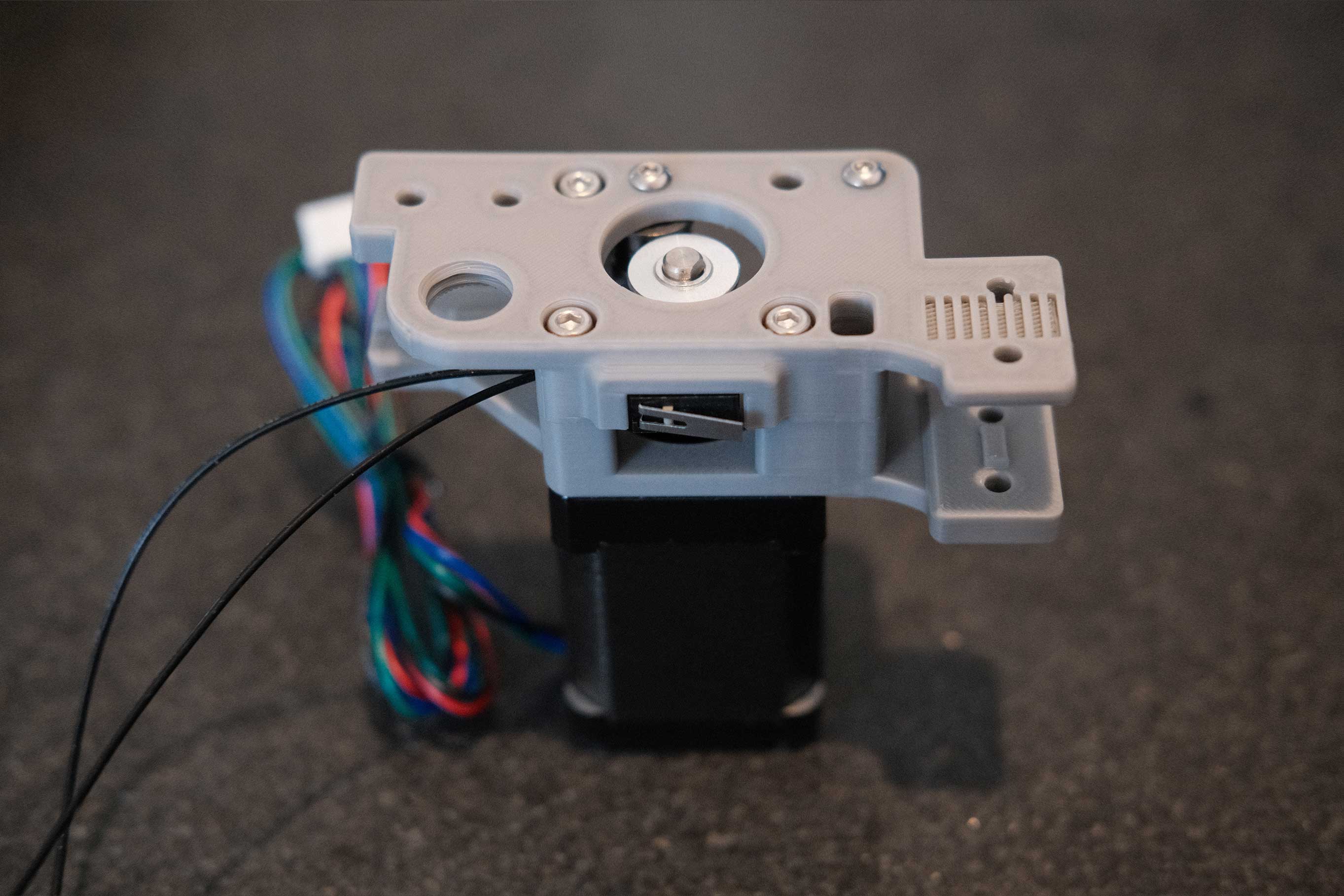
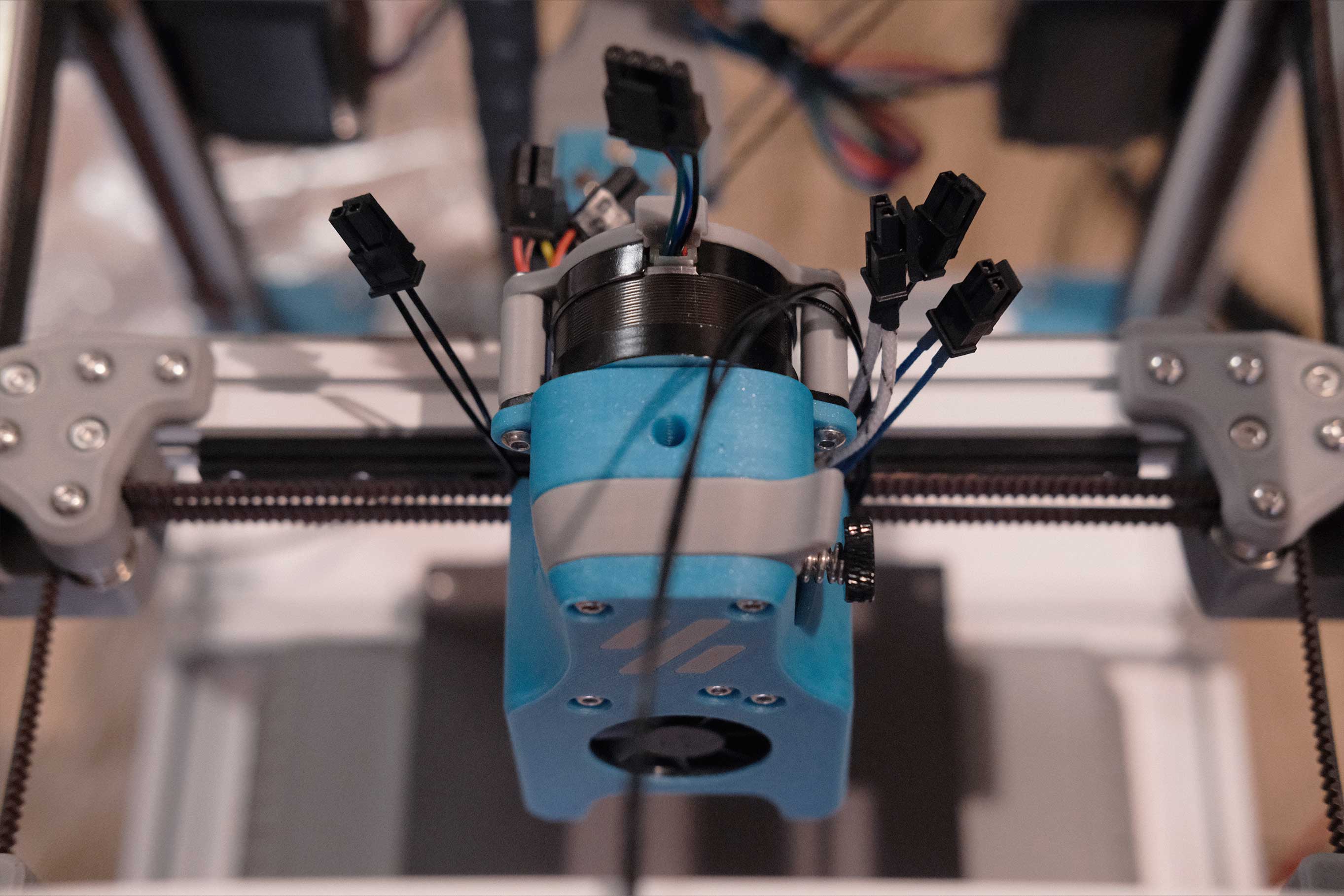
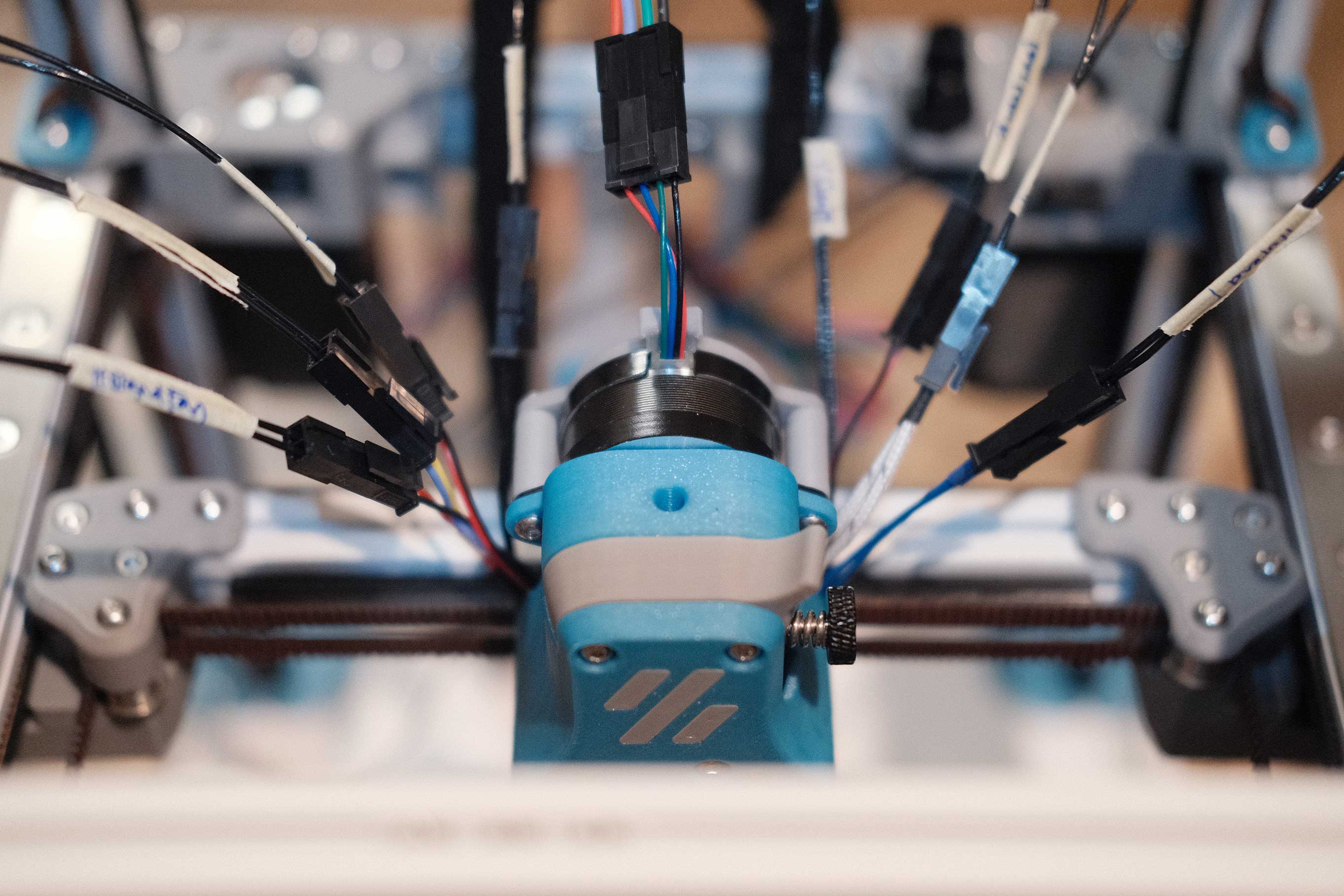
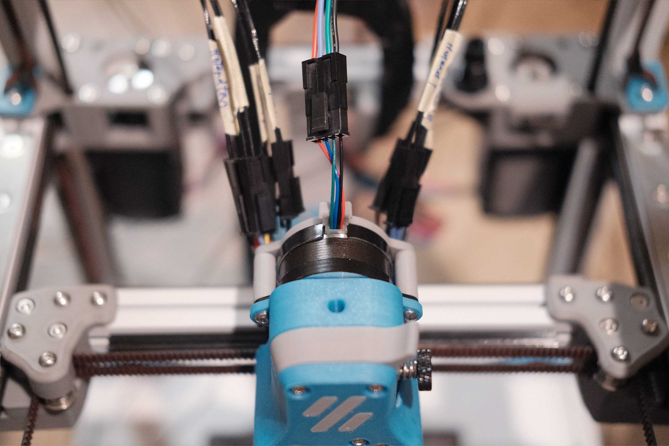
Wire connectors facing towards inside of printer.
 A Drive Top - 2
After soldering the wires and directing them into the wire channel, they naturally form 90° bends. I’ll need to add heatshrink to reinforce the connection and zip tie this up somewhere for strain relief.
 A Drive Top - 3
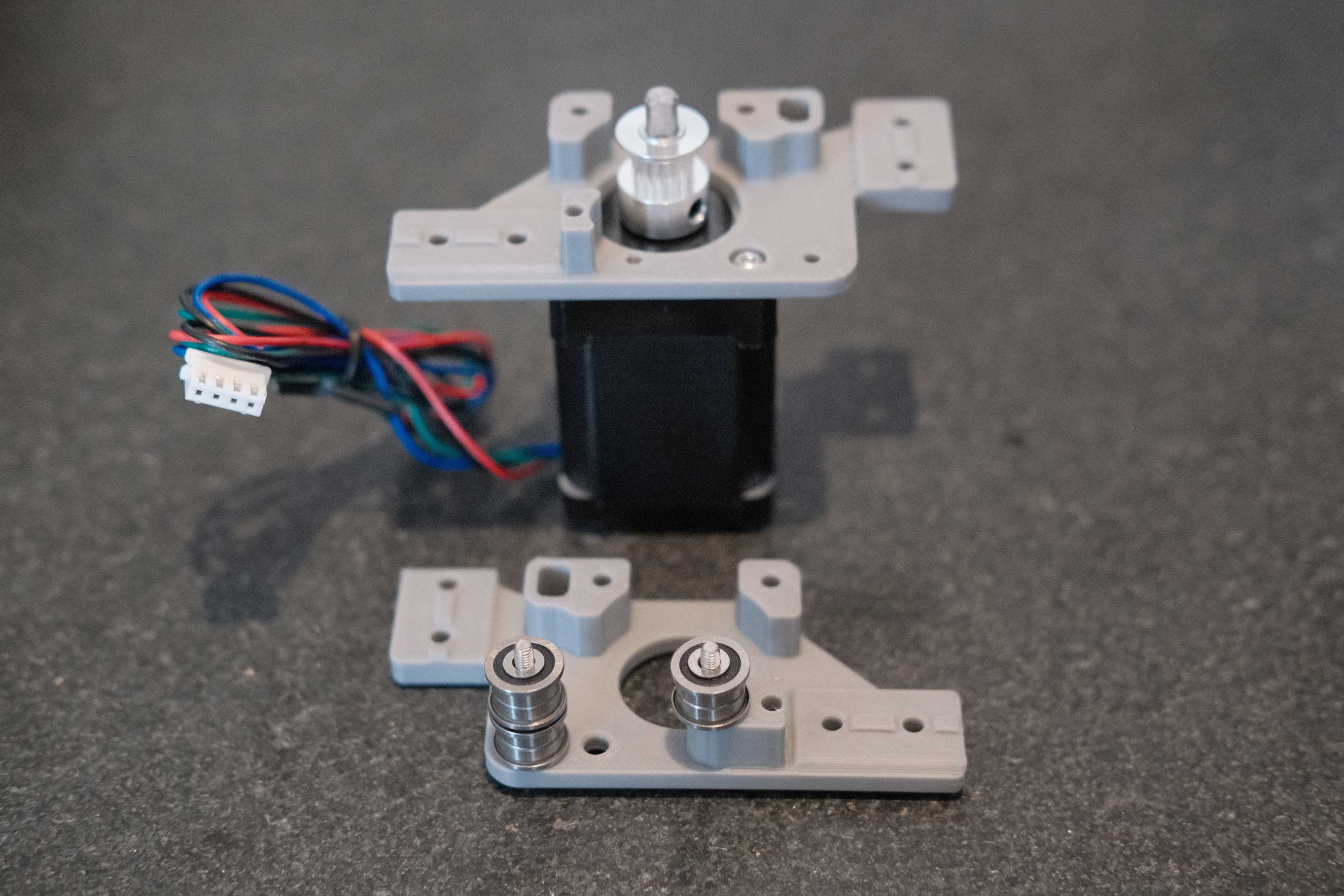
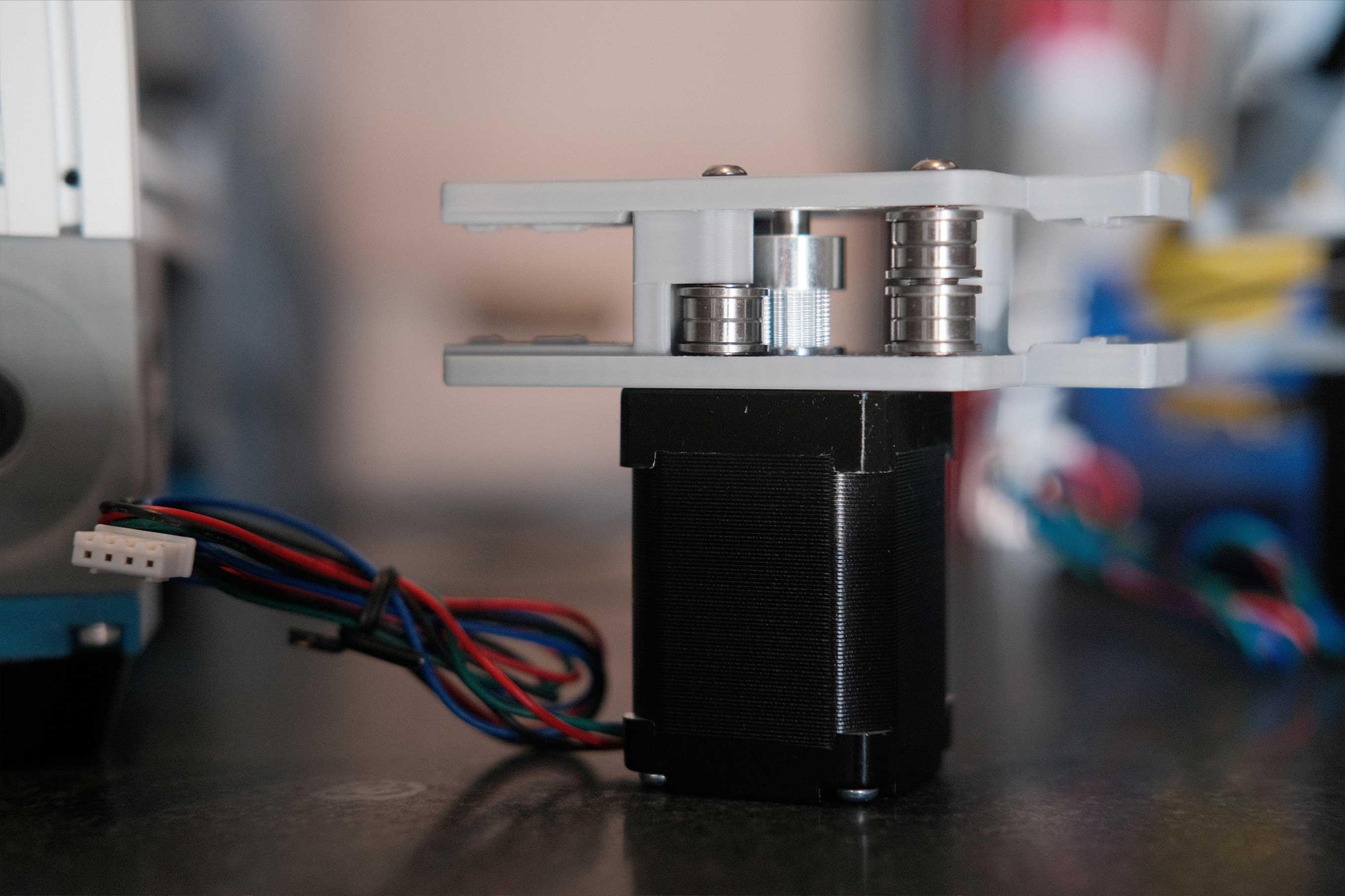
Maintaining the stacks while assembly the top and bottom together is pretty tricky.
 A Drive - 4
 A Drive - 5
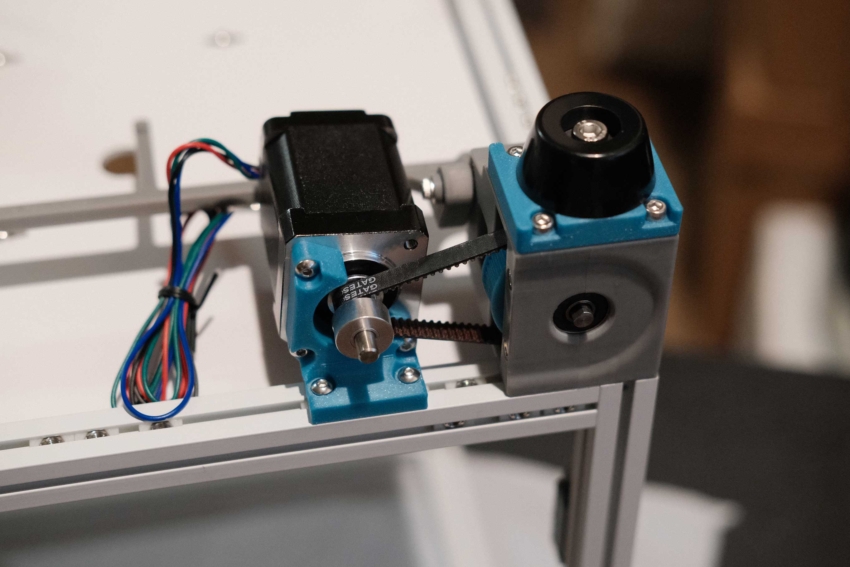
Adjust the A pulley so that the teeth are centered against the top bearing stack, then loctite and tighten the grub screws.
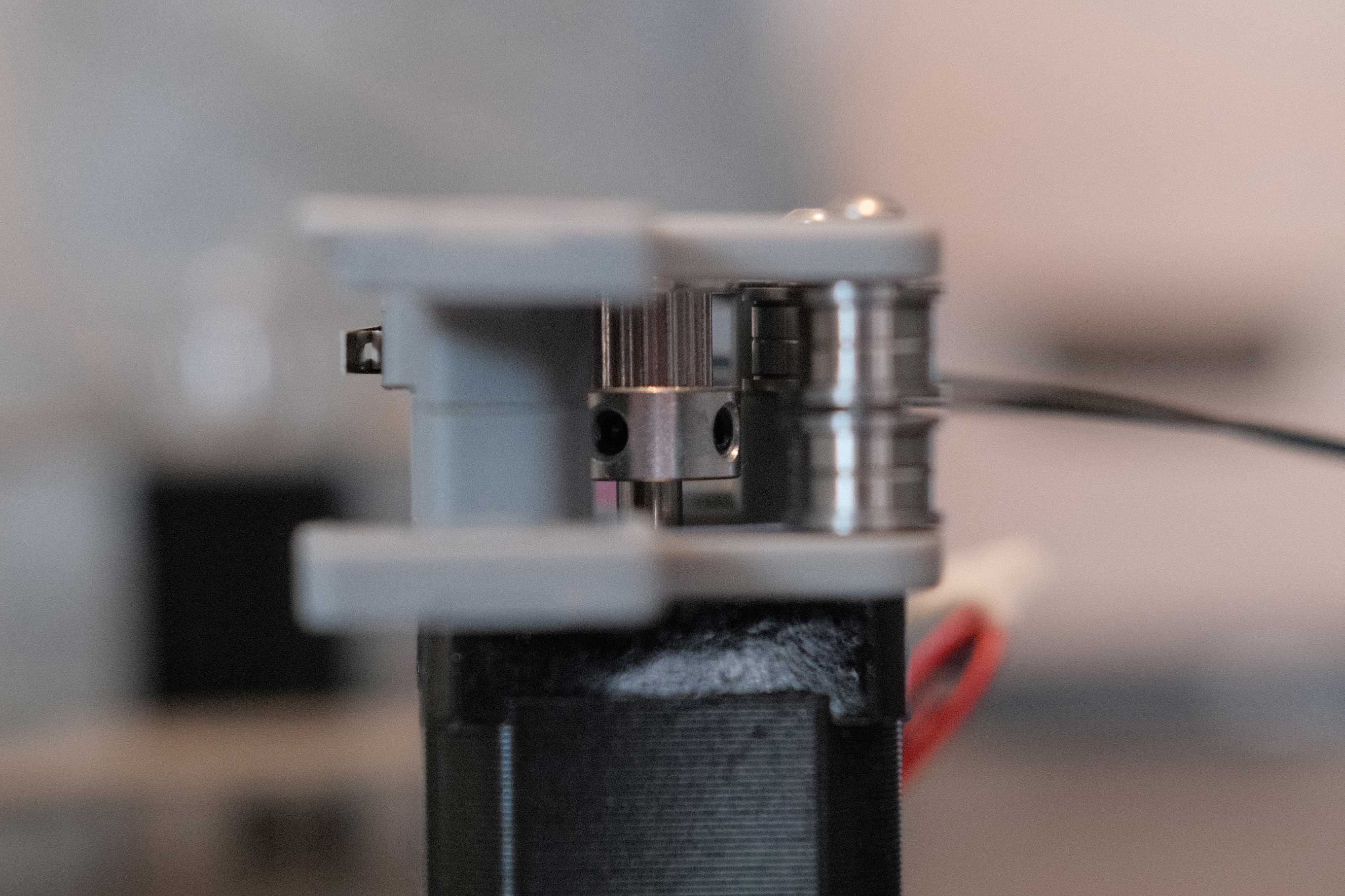 A Drive Top - 6
 B Drive - 1
Adjust the B pulley so that the teeth are centered against the bottom bearing stack, then loctite and tighten the grub screws.
 B Drive - 2
 A/B Drives - 1
X/Y Joint Assemblies
 XY Joint Assemblies - 1
It’s easier to get the parts to mate up if you give the screws some slack.
 XY Joint Assemblies - 2
 XY Joint Assemblies - 3
 XY Joint Assemblies - 4
 XY Joint Assemblies - 5
Y Endstop
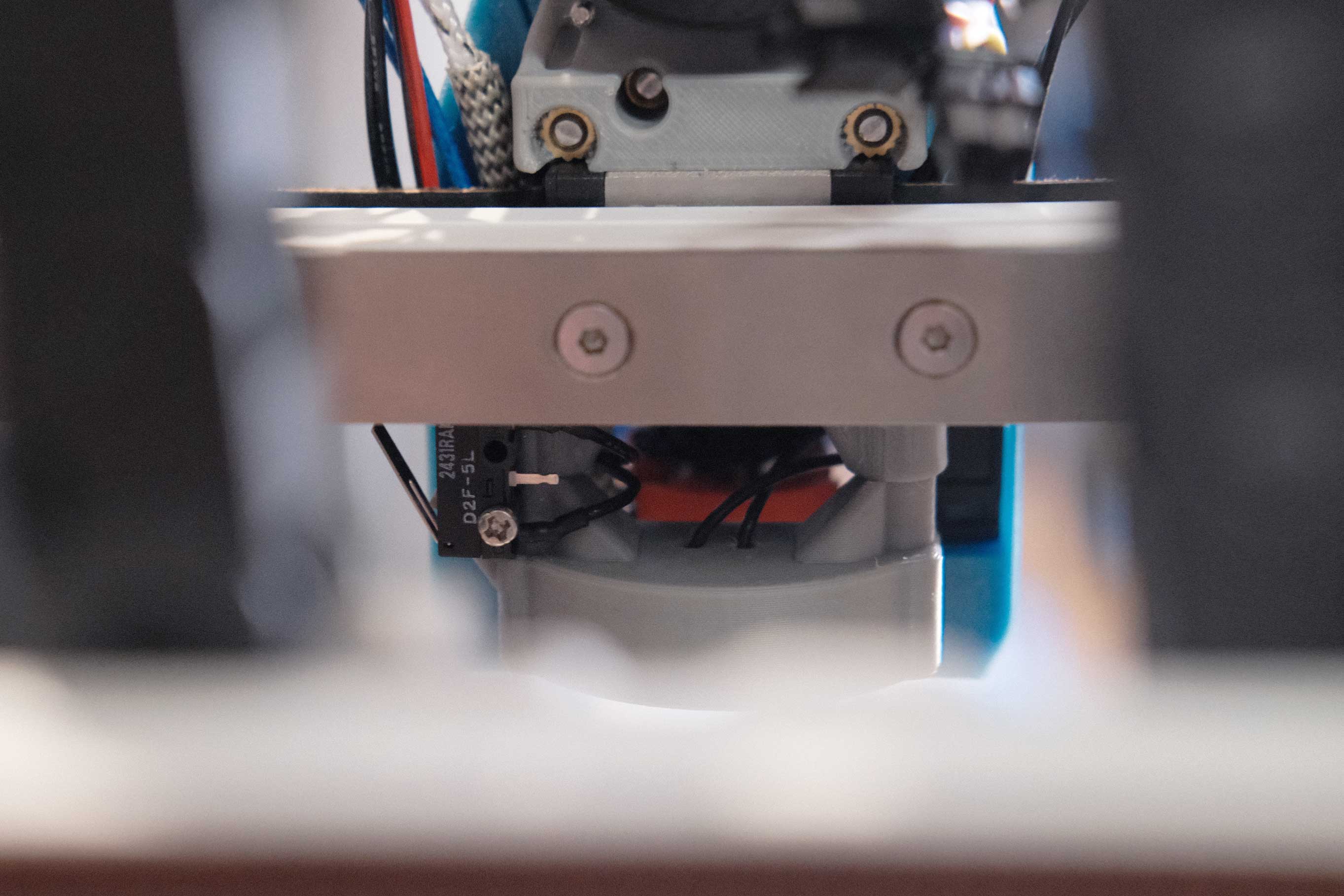
Inset the endstop 8mm from the end of the aluminum extrusion.
 Y Endstop - 1
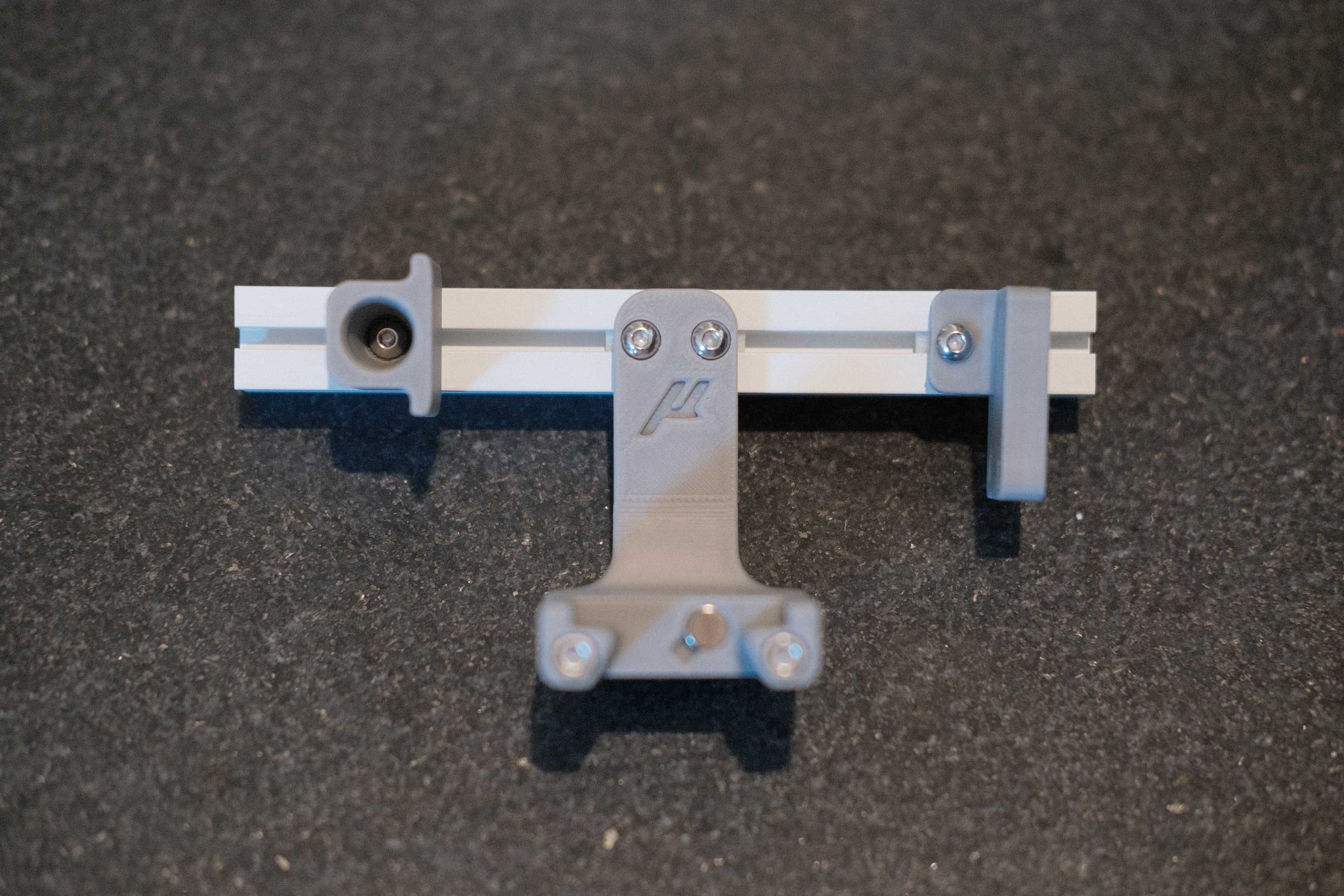
Gantry - Mounting A/B Idlers
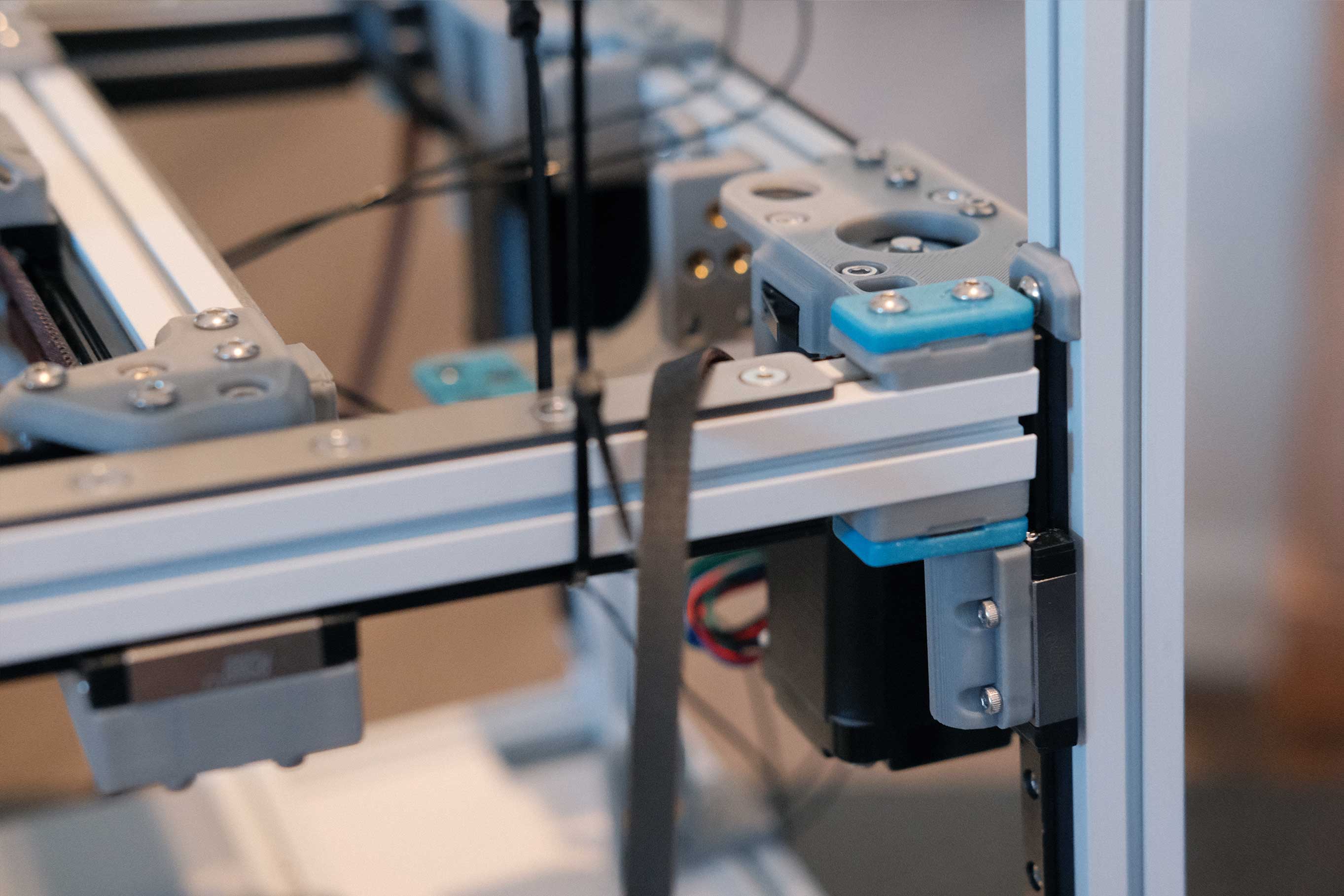
The belt clamps have a recess to accept the belt. That should face downwards.
 Gantry - Mounting A/B Idlers - 1
The belt tensioners should have the heads of their SHCS on top.
 Gantry - Mounting A/B Idlers - 2
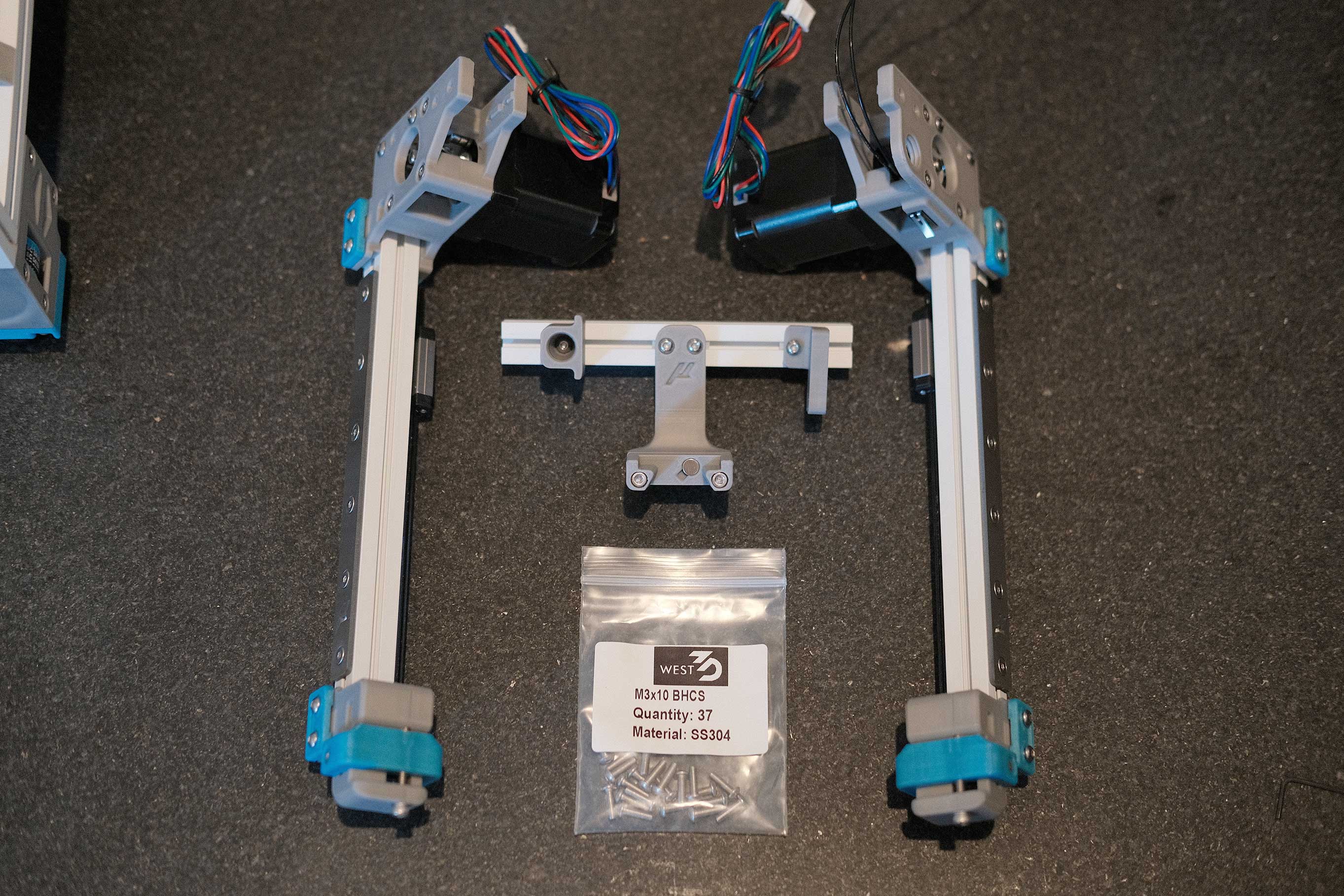
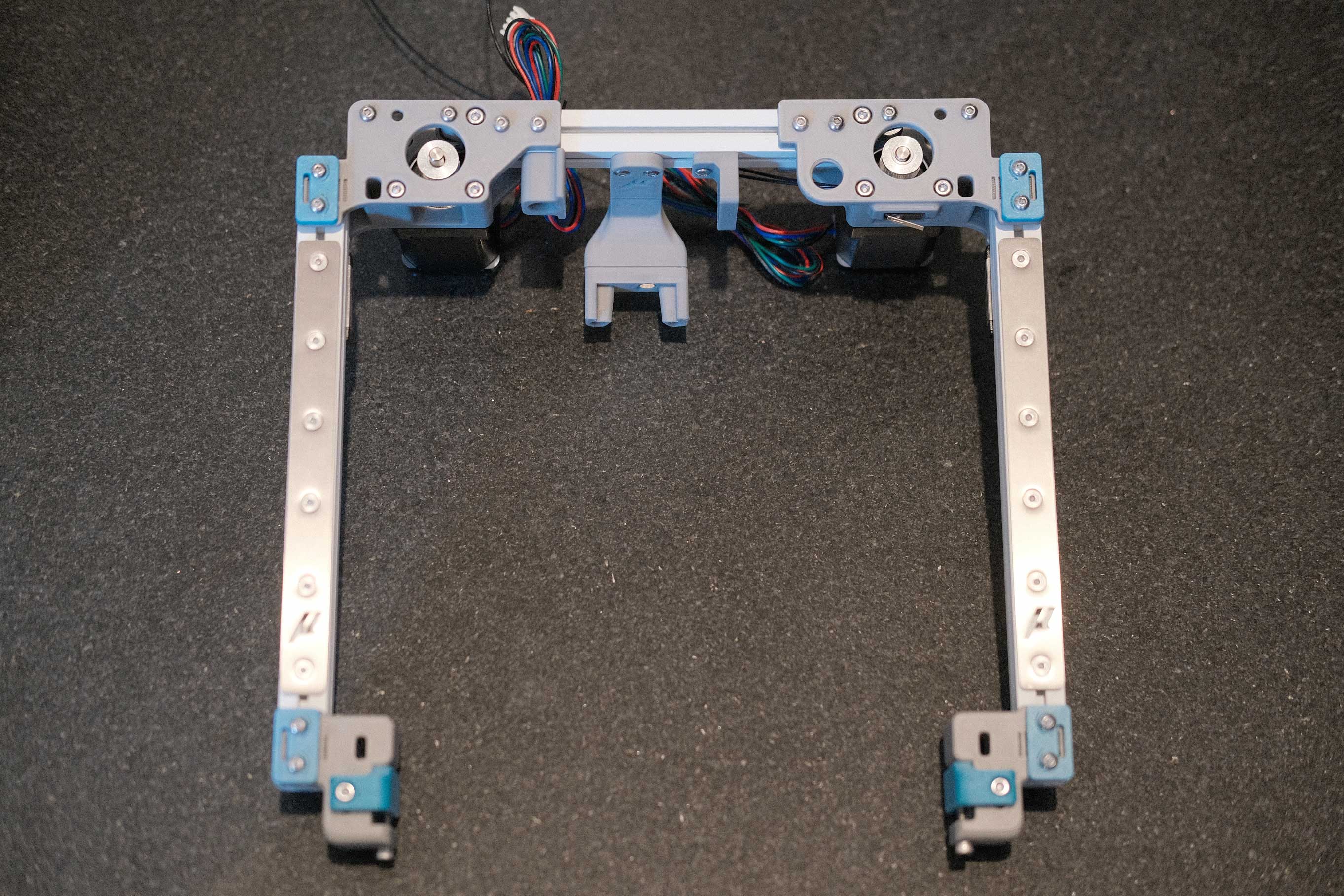
Mounting A/B Drives
 Mounting A/B Drives - 1
Klicky
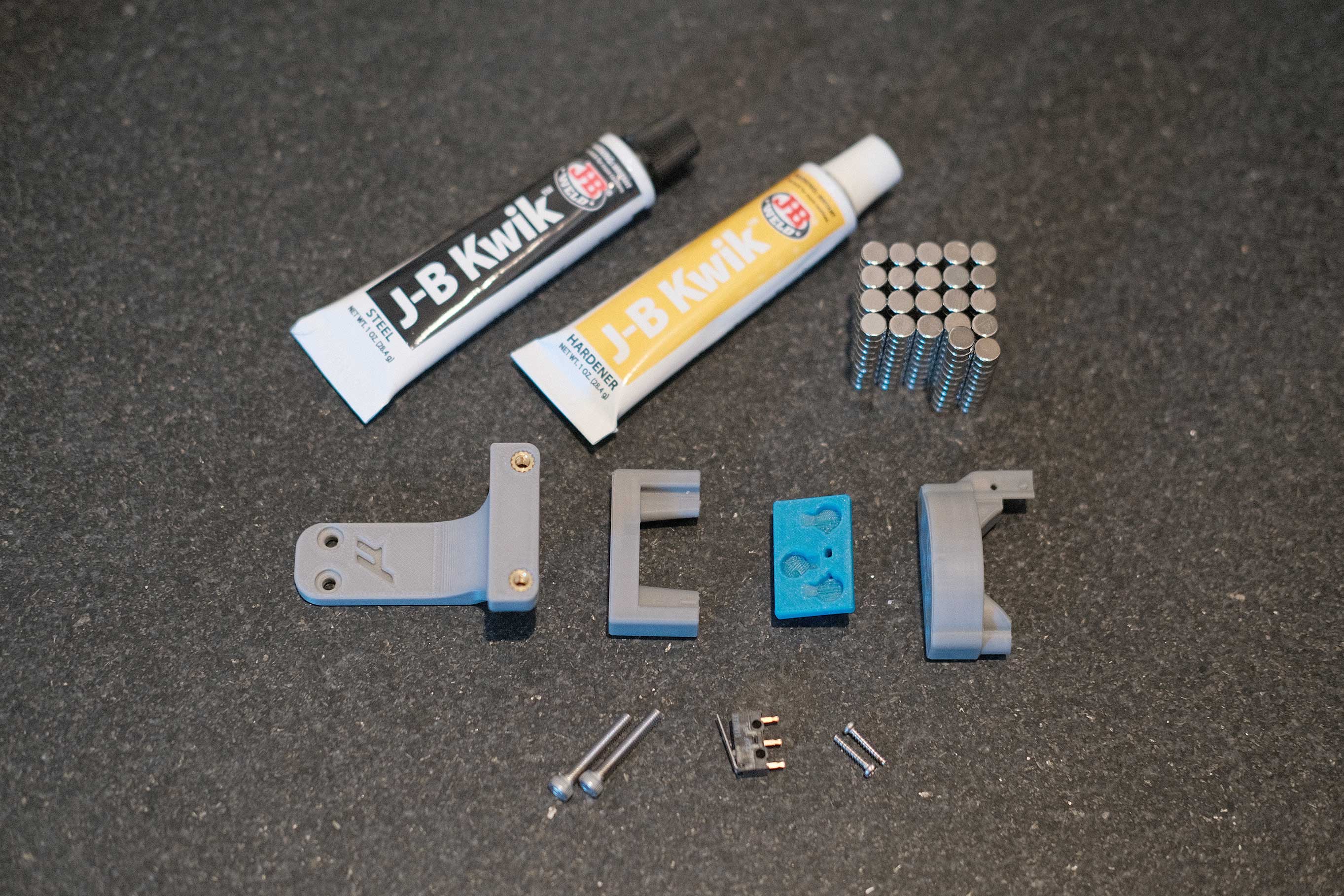
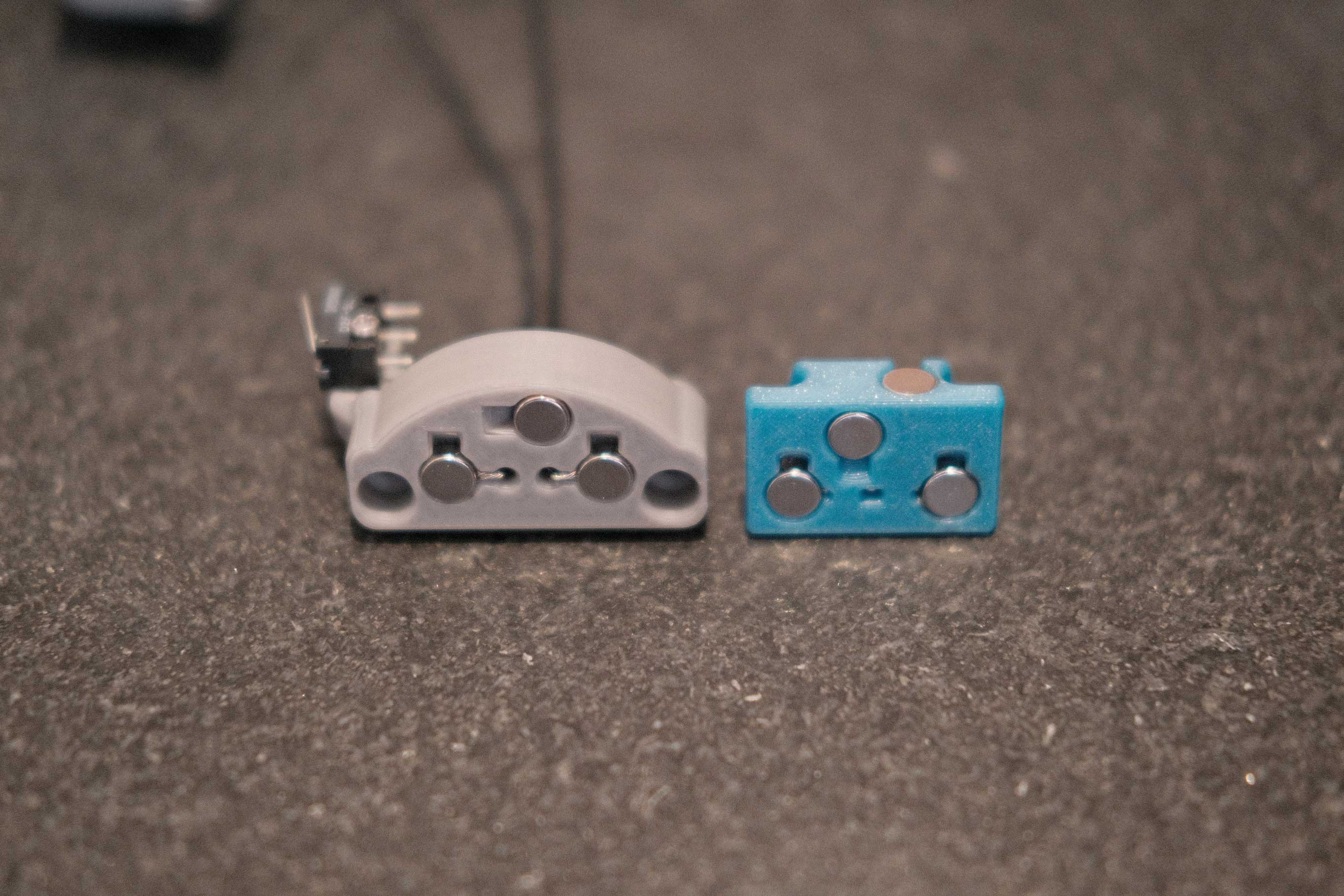
You don’t need this many 6x3 magnets. Probably.
 Klicky - 1
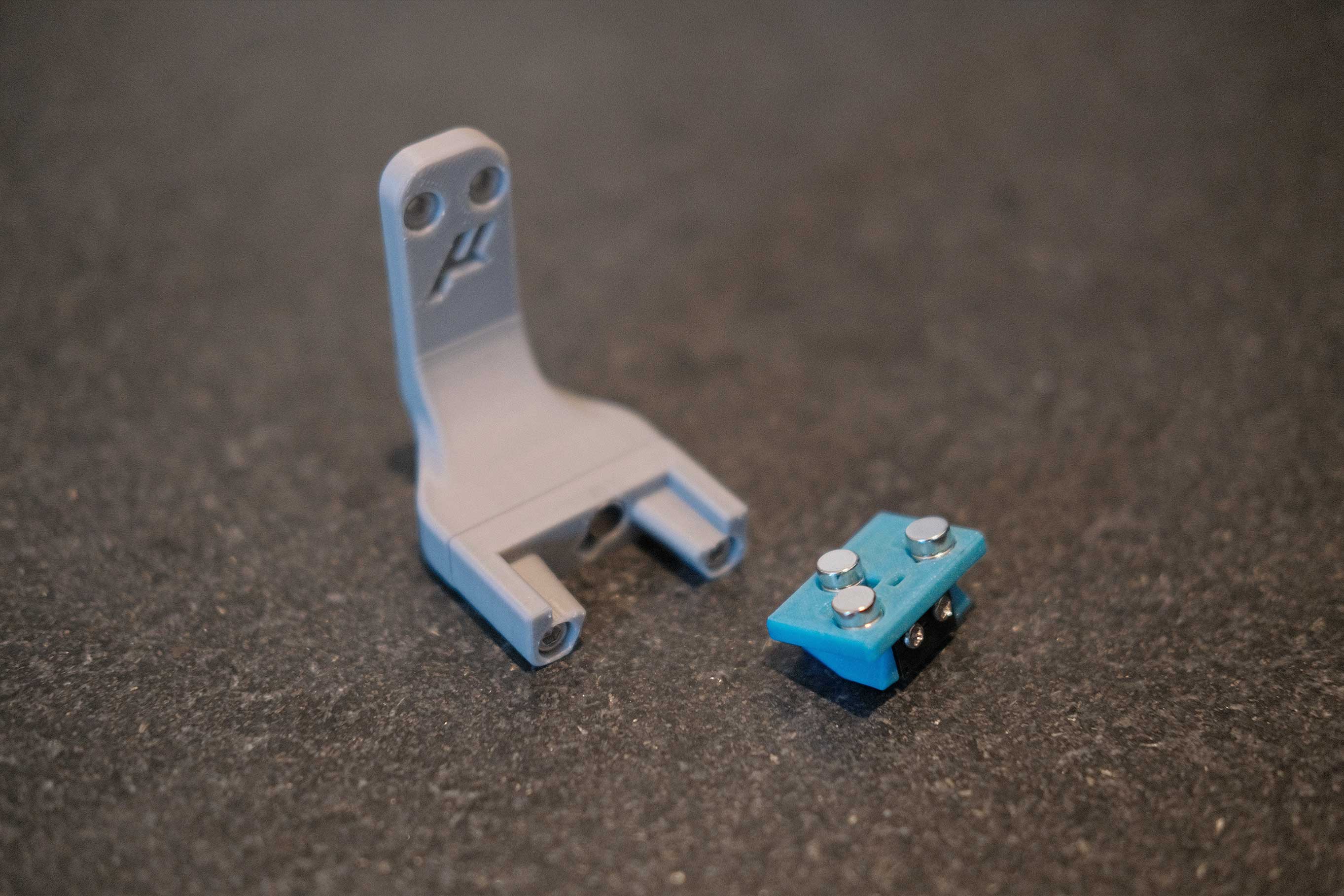
I like this implementation. The switch leads just poke through the printed piece and touch the magnets. Passes my multimeter continuity test.
 Klicky - 2
On the carriage mount (left), you can see how the magnets press into the exposed wires, completing the circuit when the probe is grabbed. The two wired magnets are the same polarity, while the non-wired magnet is opposite.
 Klicky - 3
 Klicky - 4
 Klicky - 5
Rear Gantry
I’m using leftover 10x11 cable chain, so the mount here is not the default Micron one.
 Rear Gantry - 1
 Rear Gantry - 2
 Rear Gantry - 3
 Rear Gantry - 4
Mounting X Axis
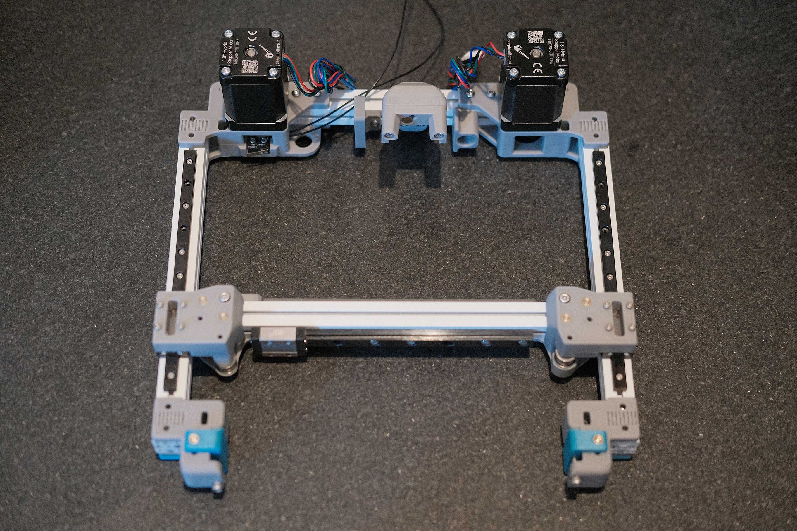 Mounting X Axis - 1
 Mounting X Axis - 2
X/Y Belts
 X/Y Belts - 1
None of the screws holding parts to aluminum rails are tightened yet. Pulling on the belts too hard at this point will case things to shift. We’ll do final tightening of screws and belt once the gantry is installed.
 X/Y Belts - 2
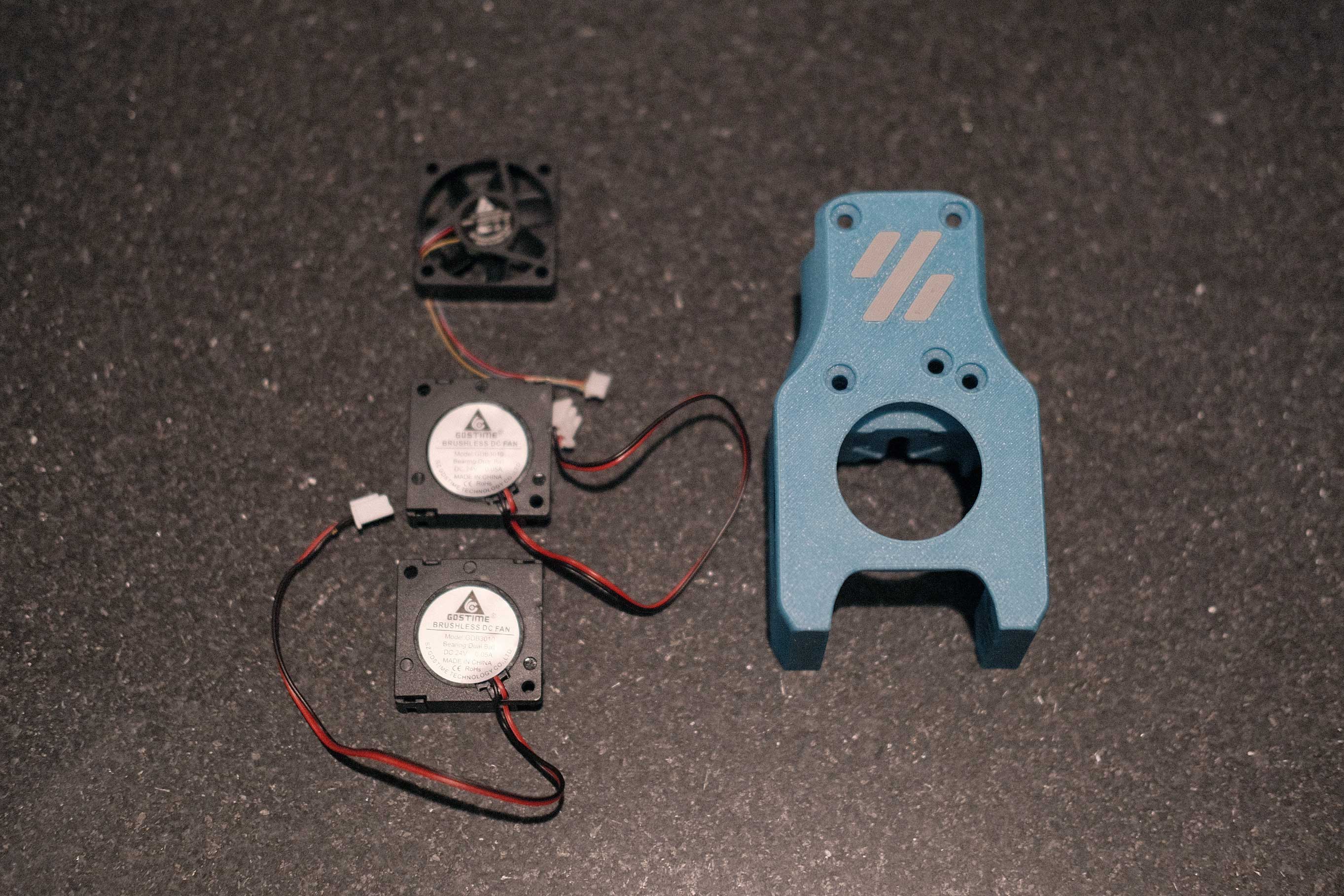
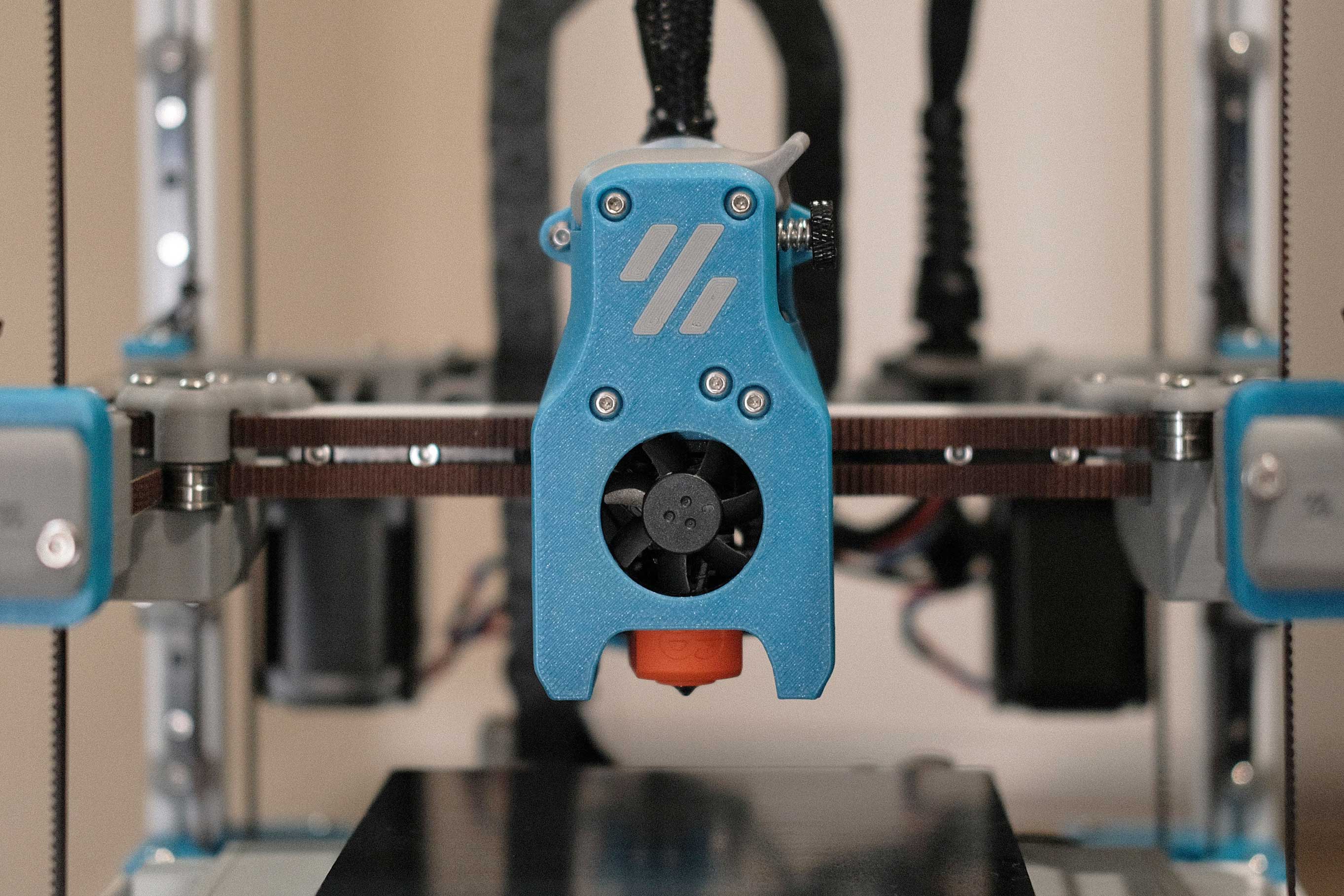
Mini Afterburner
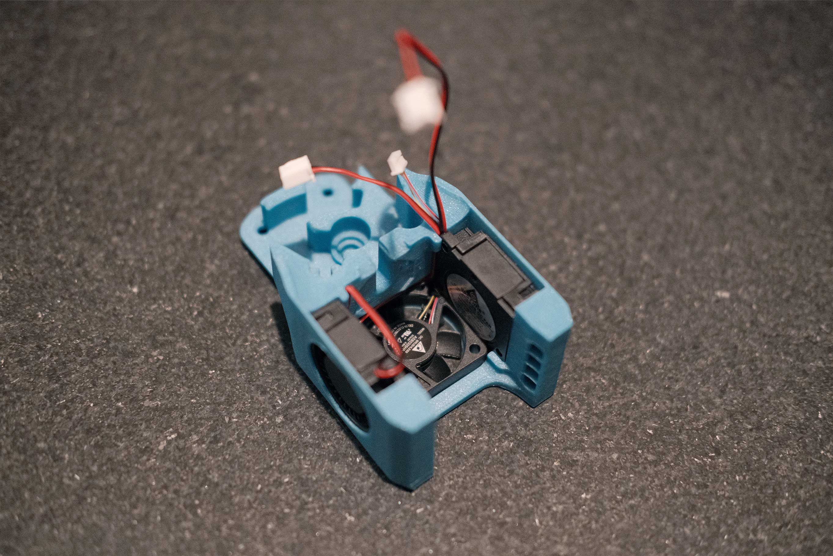
The little PTFE tube here is the wrong length. I cut it to have 7mm exposed from the printed part as shown in the manual, but this is way too short for the Dragonfly that came with the DFH kit. I later inserted the PTFE tube into the Dragonfly from the top, then measured and cut ~8mm of extension; the 7mm as requested plus a tiny bit to sit inside the printed part for alignment.
Additionally, the drive gear shaft was sticking proud about 1mm and I was worried it would rub against the extruder motor, so I spent some time with a file and knocked it down until it was flush with the printed face.
 Mini Afterburner - 1
The 3006 Delta fan that came with the DFH kit is 4-wired for power/ground/tach/PWM (product page, spec sheet and guide to install tach/PWM for Klipper), and has an impressive 5.1cfm while being only 28dB. But the wires are TINY. As you’ll see later on, I ended up splicing them to 24AWG for crimping and connecting to two 2-pin Microfits; power/ground and tach/PWM. This way, if I ever need to use a standard 2-wire fan in the future, I don’t have to deal with a weird 4-pin connector.
 Mini Afterburner - 2
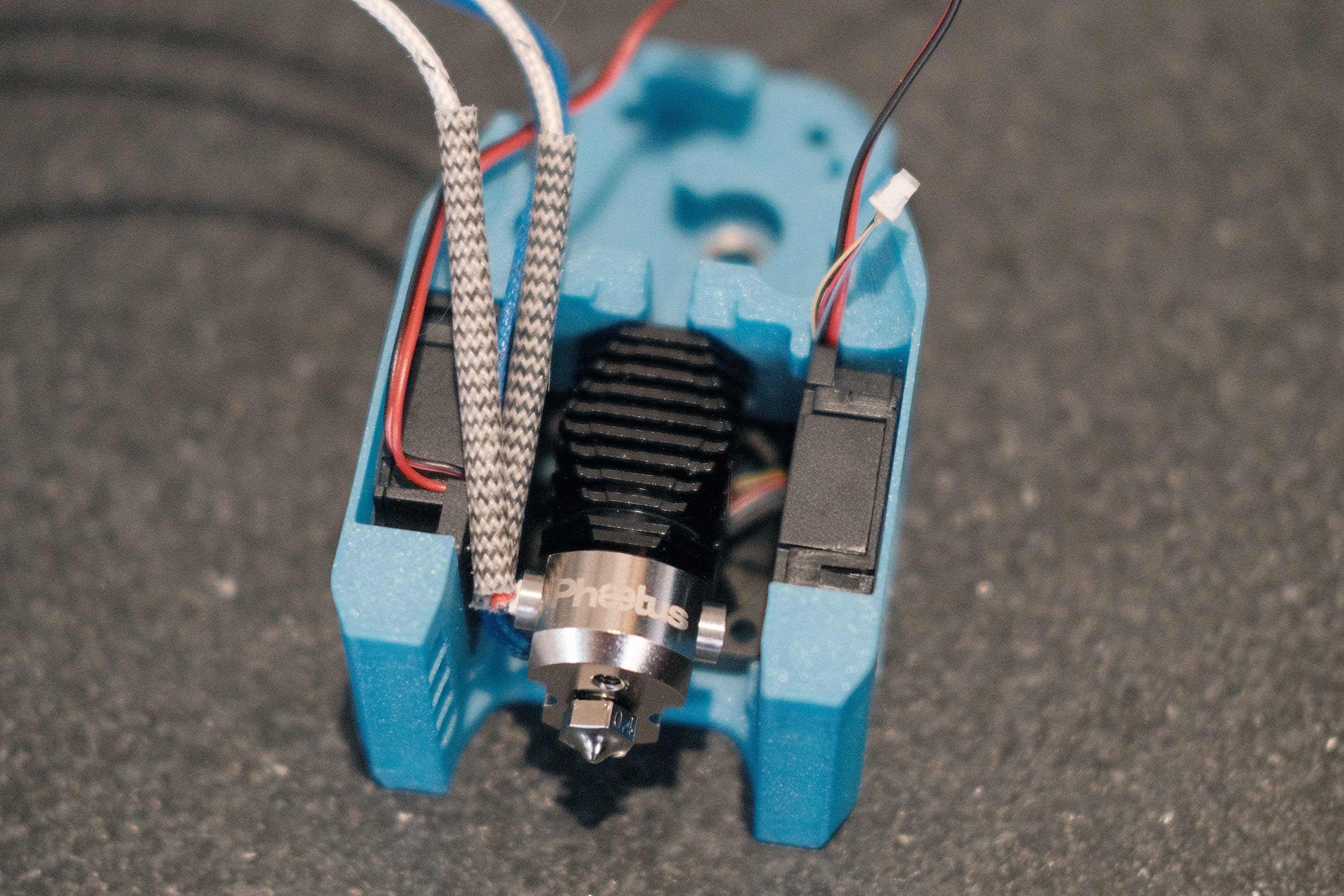
At first, I had all my fan wires exiting the wire groove, but this required wrapping the left part cooling fan wires around the hotend on the inside of the mount. I changed this after the photo, and just left the fan wires on the left to come out that same side.
 Mini Afterburner - 3
Look at how tiny those wires are. Makes standard fan wires look bulky in comparison.
 Mini Afterburner - 4
 Mini Afterburner - 5
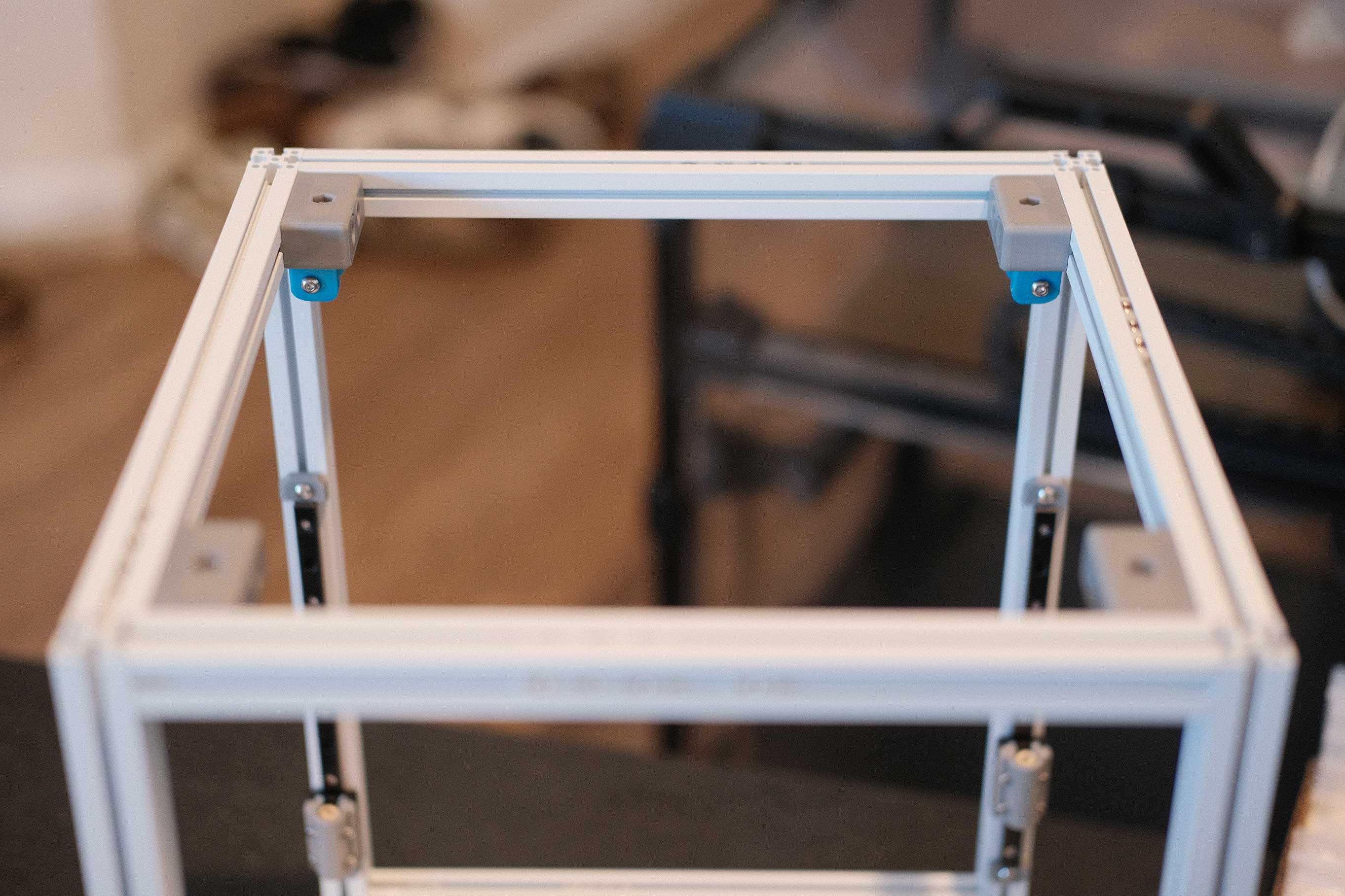
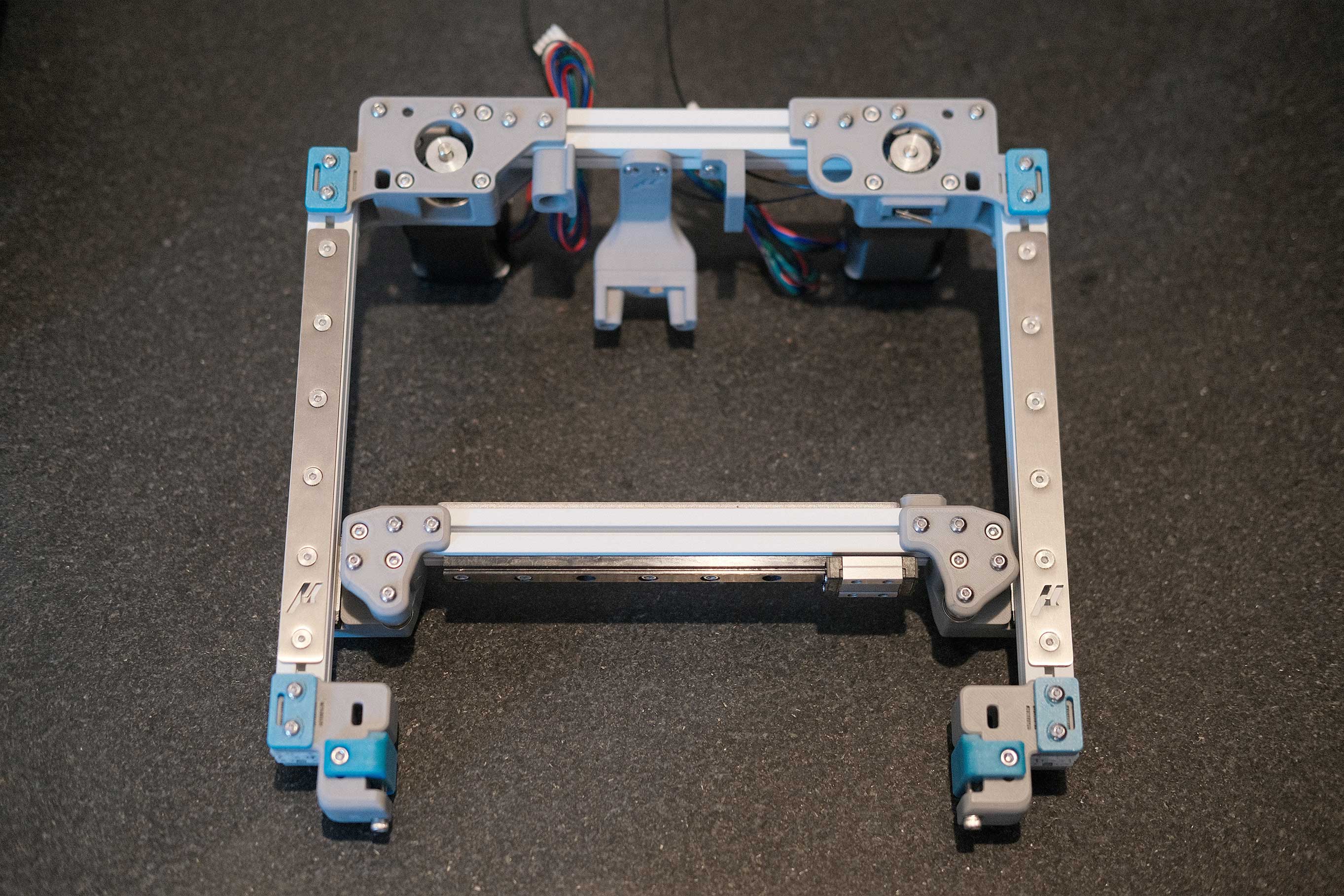
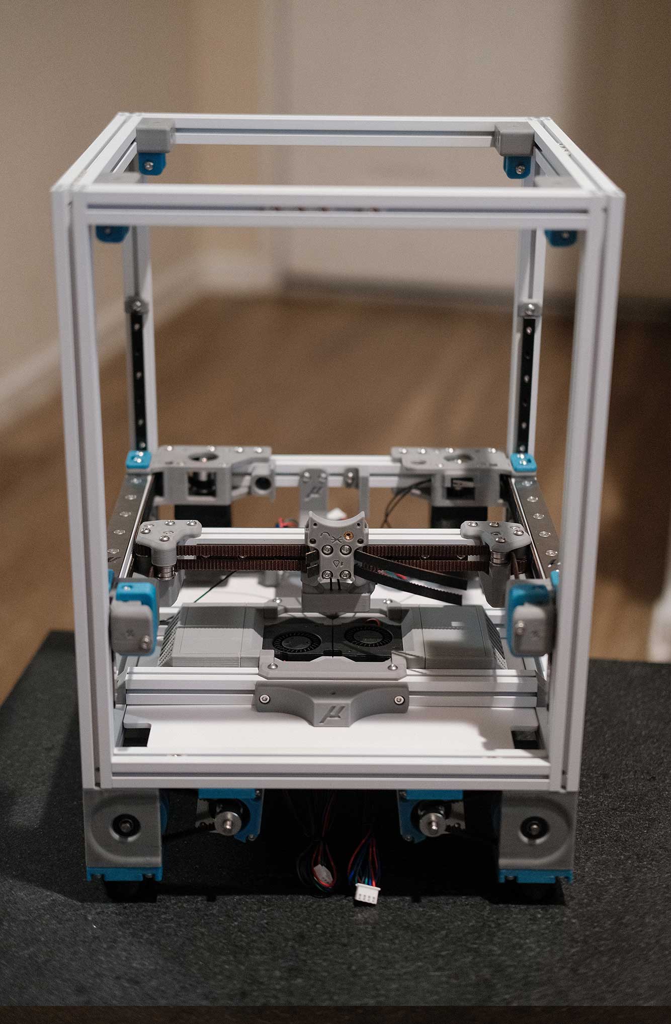
Gantry Install
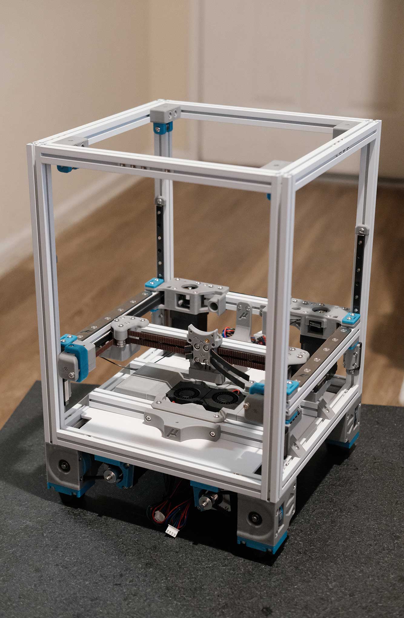
The gantry is just sitting on the linear rail carriages here to make sure everything lines up decently.
 Gantry Install - 1
 Gantry Install - 2
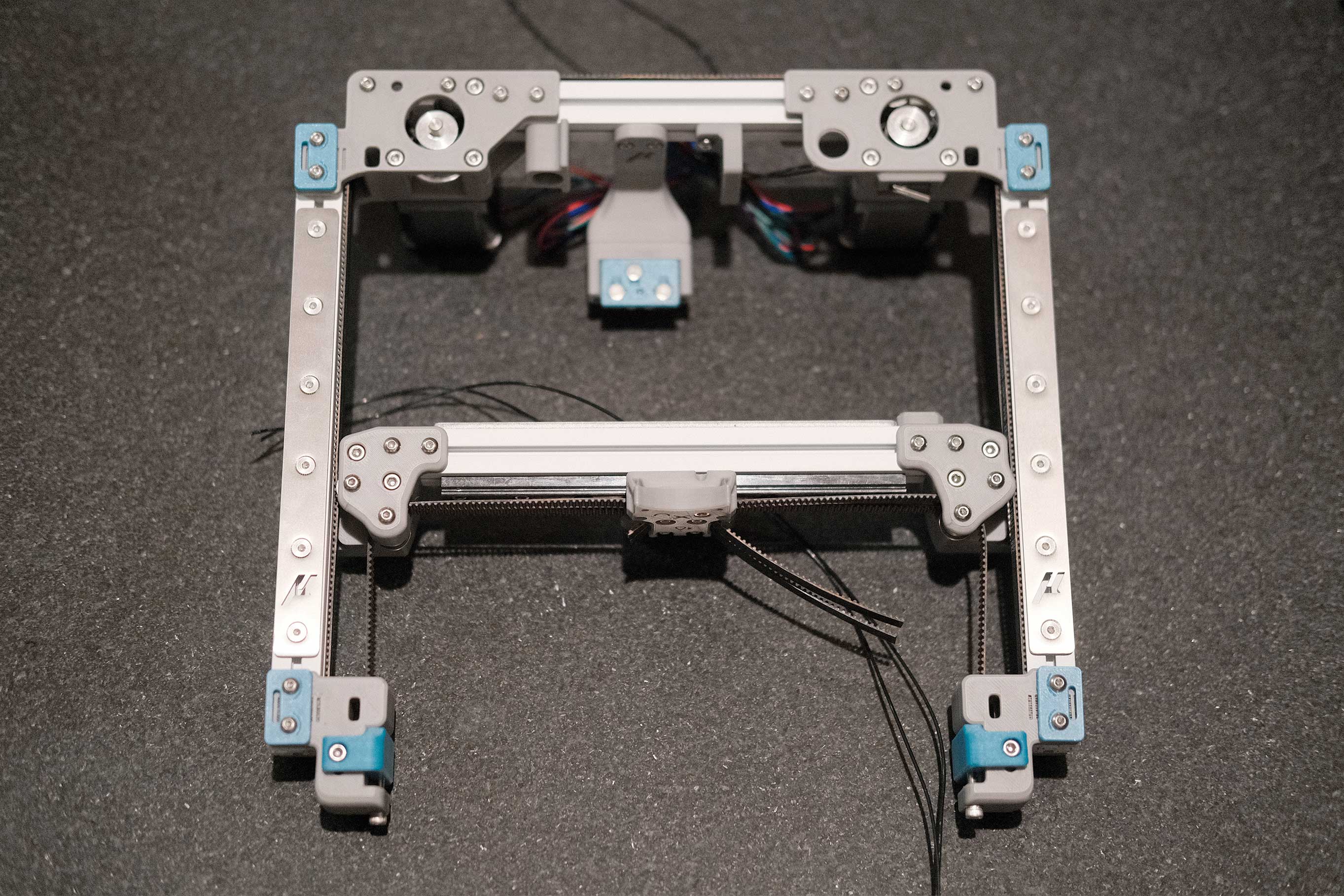
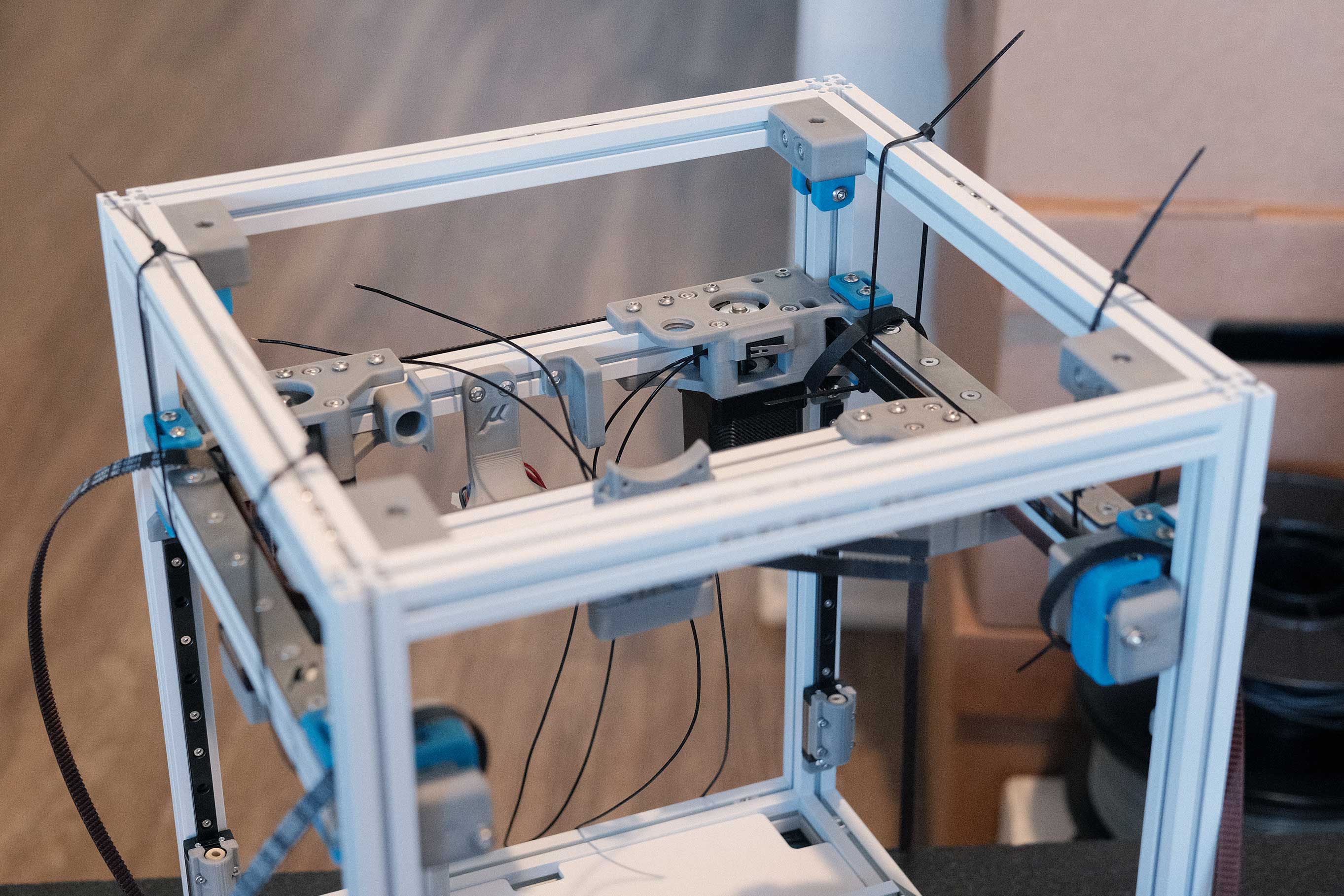
Take the gantry back out and secure the Z belts to the undersides of each corner. Get it “flying” with zip ties.
 Gantry Install - 3
Z Belts
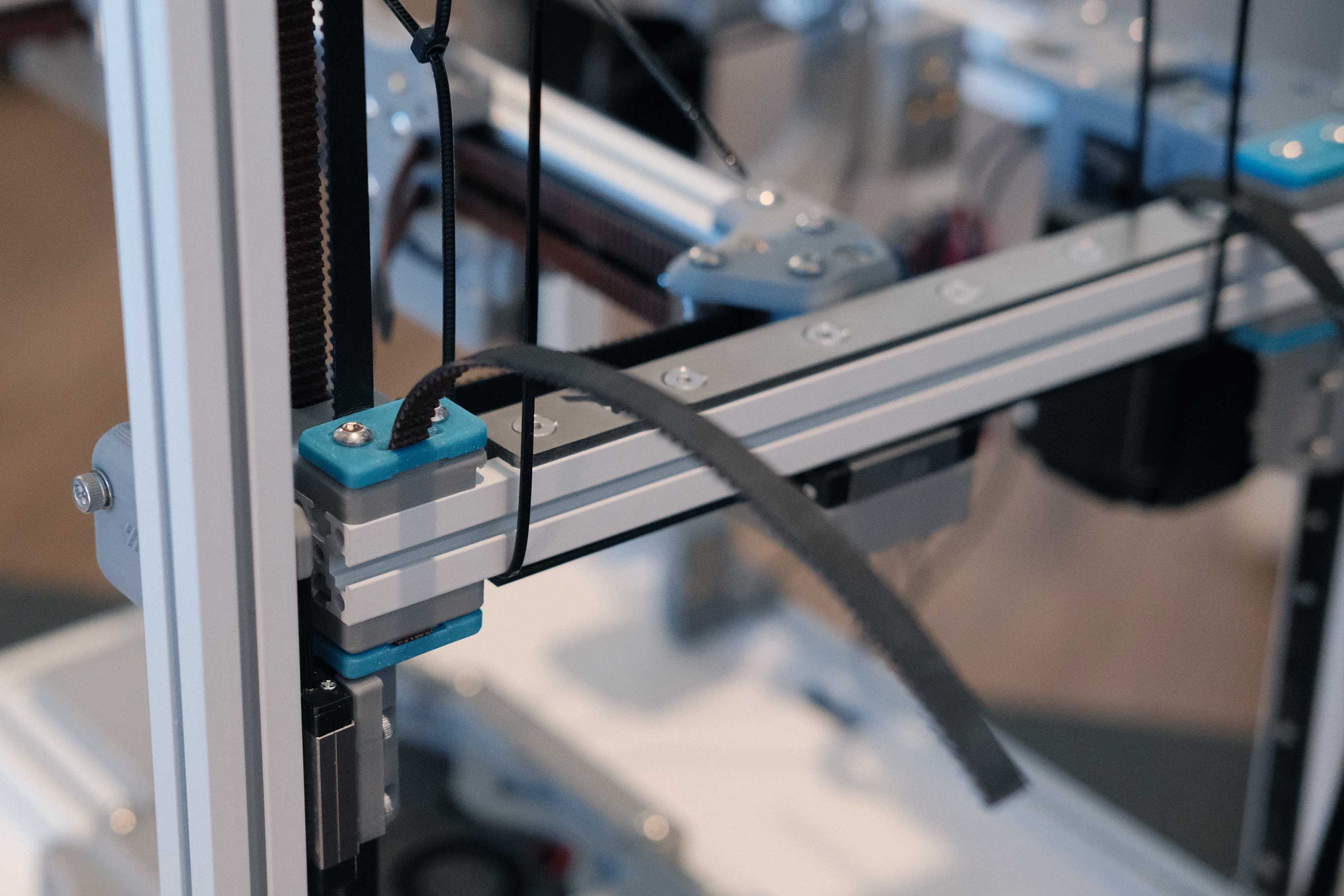
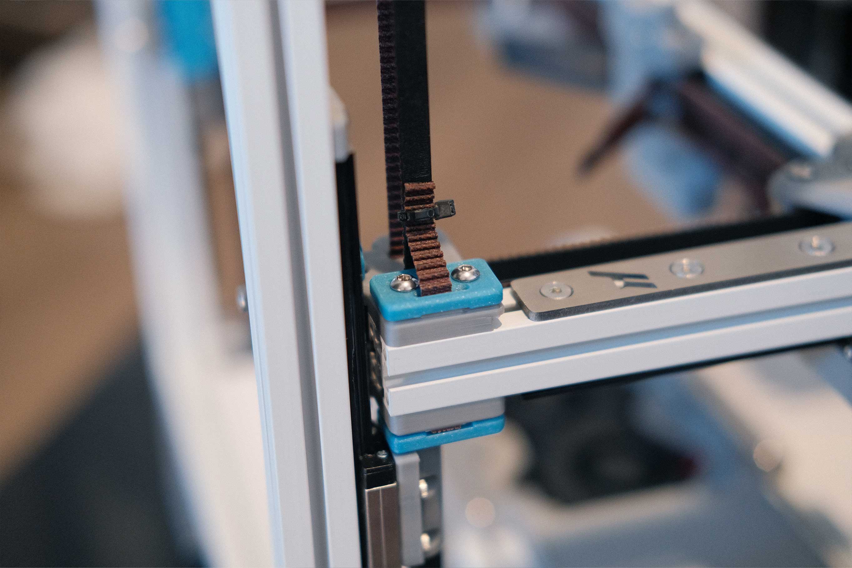
The Z belts should be secured with the bottom clamp, feeding in towards the chamber. Route it down through the Z assembly pulleys, back up through the slot in the X/Y tensioners (just passing through, not actually interacting with the X/Y parts), through the top idlers, and back down to be secured with the top clamp.
 Z Belts - 1
Extra belt slop can be fed through the “mouth”. Tightening this clamp down will pull the belt just a bit tighter. It will take trial and error and adjusting one or two teeth at a time to get the 4 corners at equal tension.
 Z Belts - 2
I left enough belt length to work with in the future. Finally, zip tie to tidy up.
 Z Belts - 3
X/Y Belts (Revisited)
Now’s the time to pull the X/Y belts snug, doublecheck for squareness, check for binding/racking in the moveents, tighten up the gantry frame, and cut the belts to length. Flush enough to make me nervous. Also, getting the belt snug enough for the tensioners to set final tension was actually pretty tricky.
 X/Y Belts (Revisited) - 1
All Belts Done
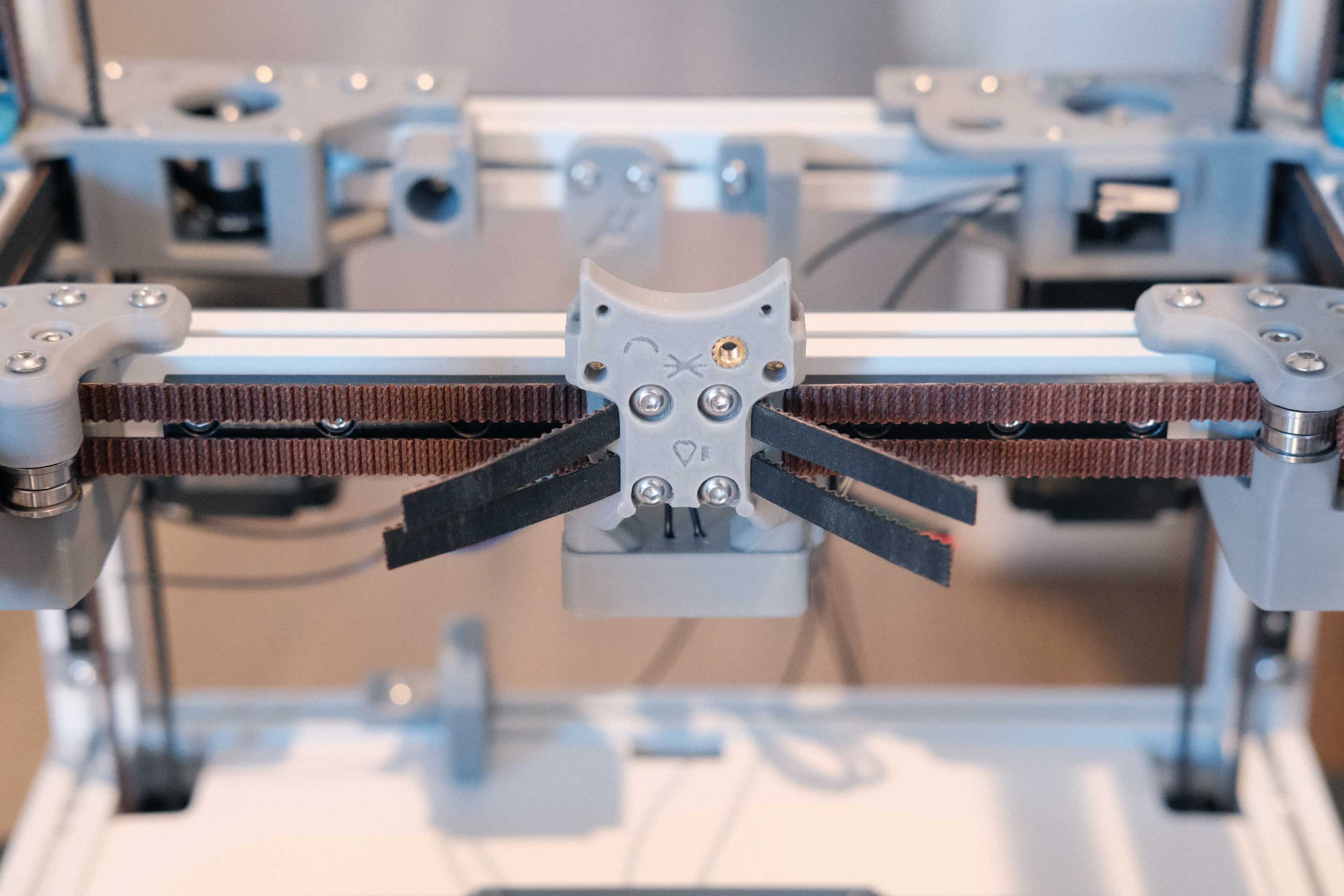
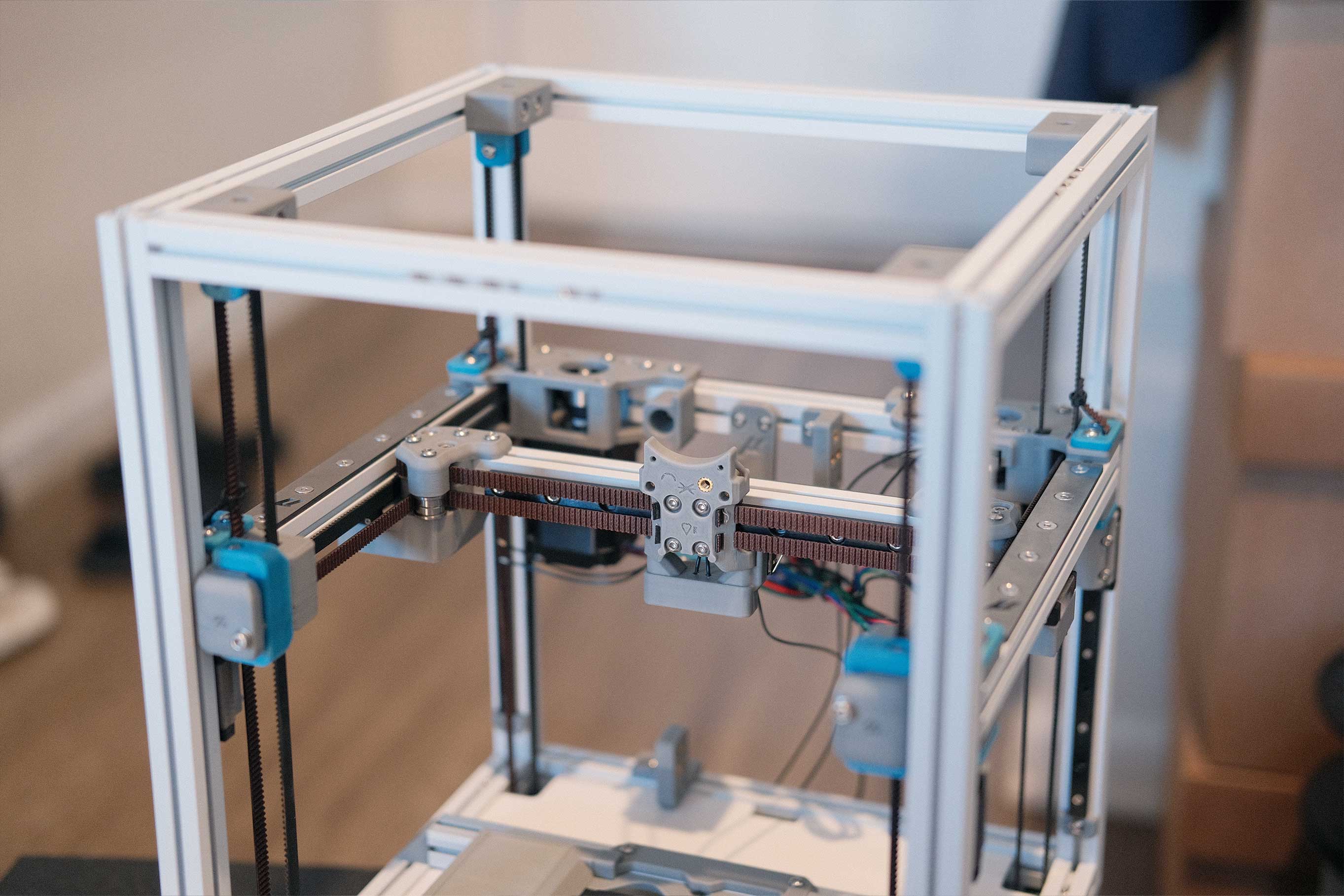
Tensioned, trimmed to final lengths, and cleaned up.
 All Belts Done - 1
Mini Afterburner (Revisited)
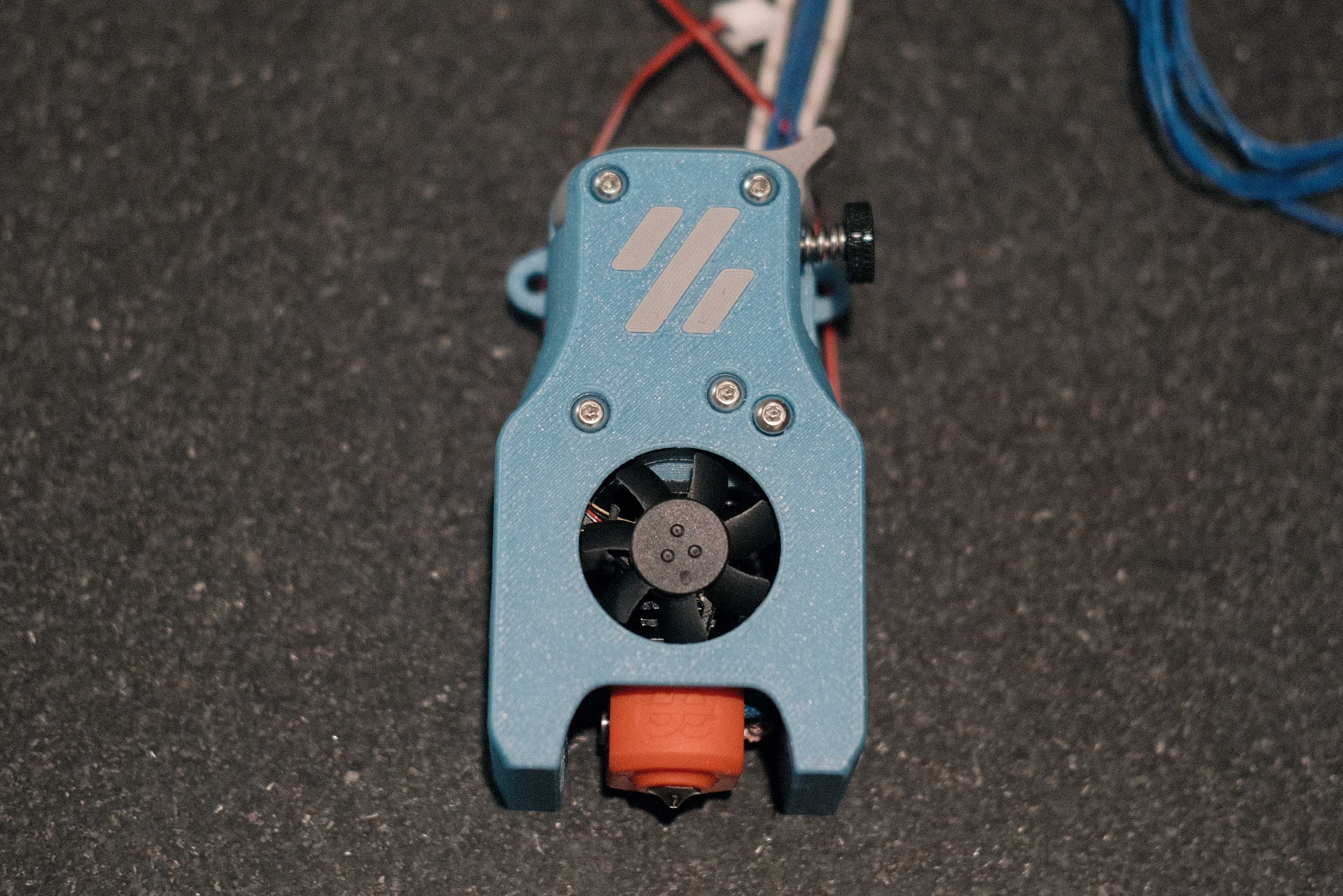
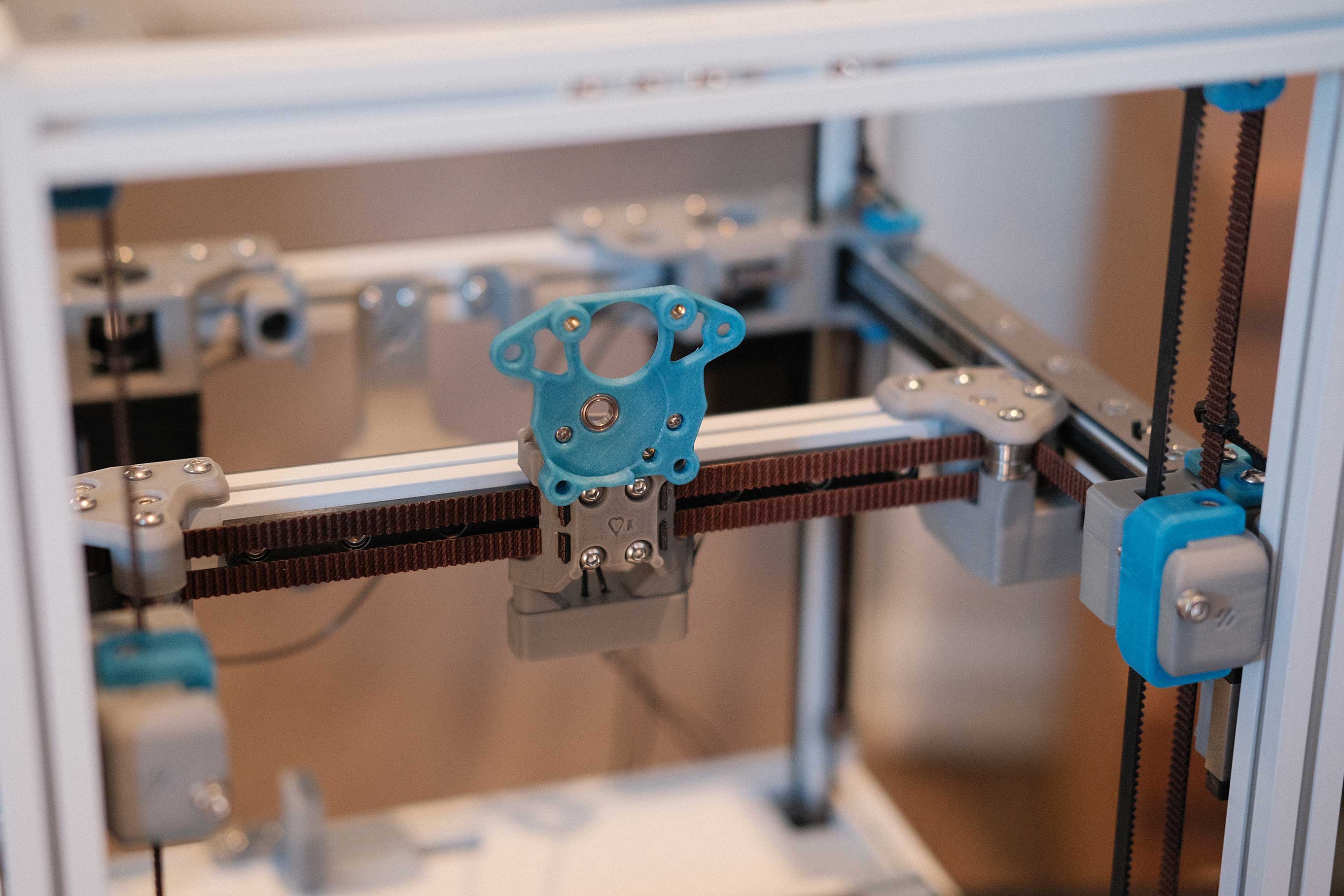
Install the toolhead mount.
 Mini Afterburner (Revisited) - 1
Test-fitting the toolhead. (I still haven’t cut the toolhead wires to length yet.)
 Mini Afterburner (Revisited) - 2
Front Skirt
These use the easier-to-print Z motor covers, though I did print the originals and they came out just fine. Spend the time to orient the seam to sit at the bottoms.
 Front Skirt - 1
 Front Skirt - 2
Woooo, finally! Still a rat’s nest of wires, but seeing the final colors together is exciting!
 Front Skirt - 3
Electronics
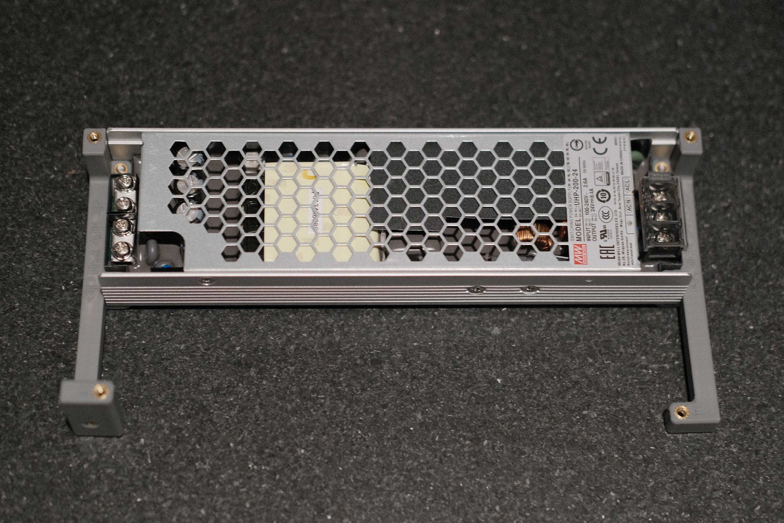
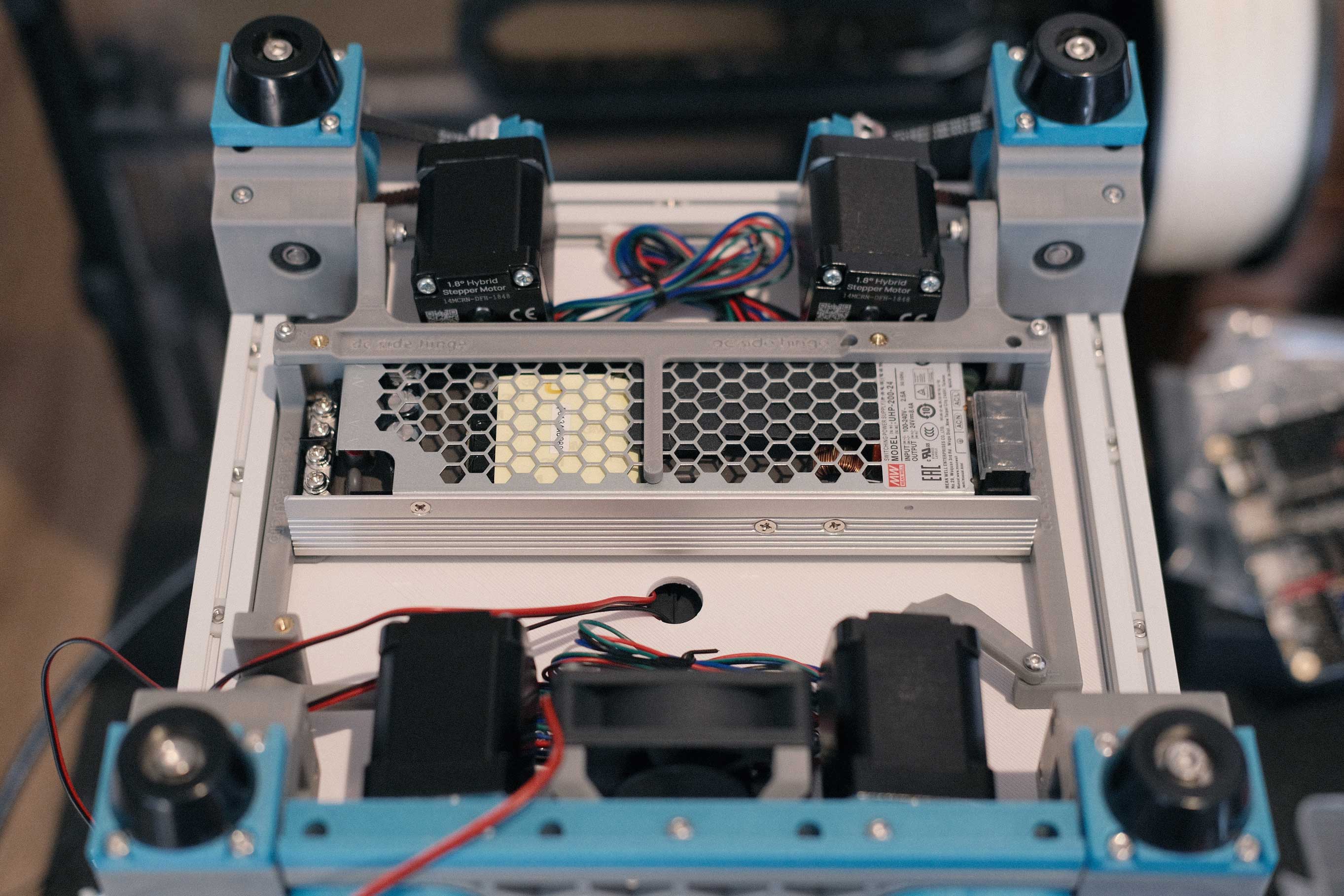
AC goes on on the left, DC exits on the right.
 Electronics - 1
This lever locks the hinged frame to the aluminum rail. (I later reprint this in Electrolytic Deuterium to make it stand out more.)
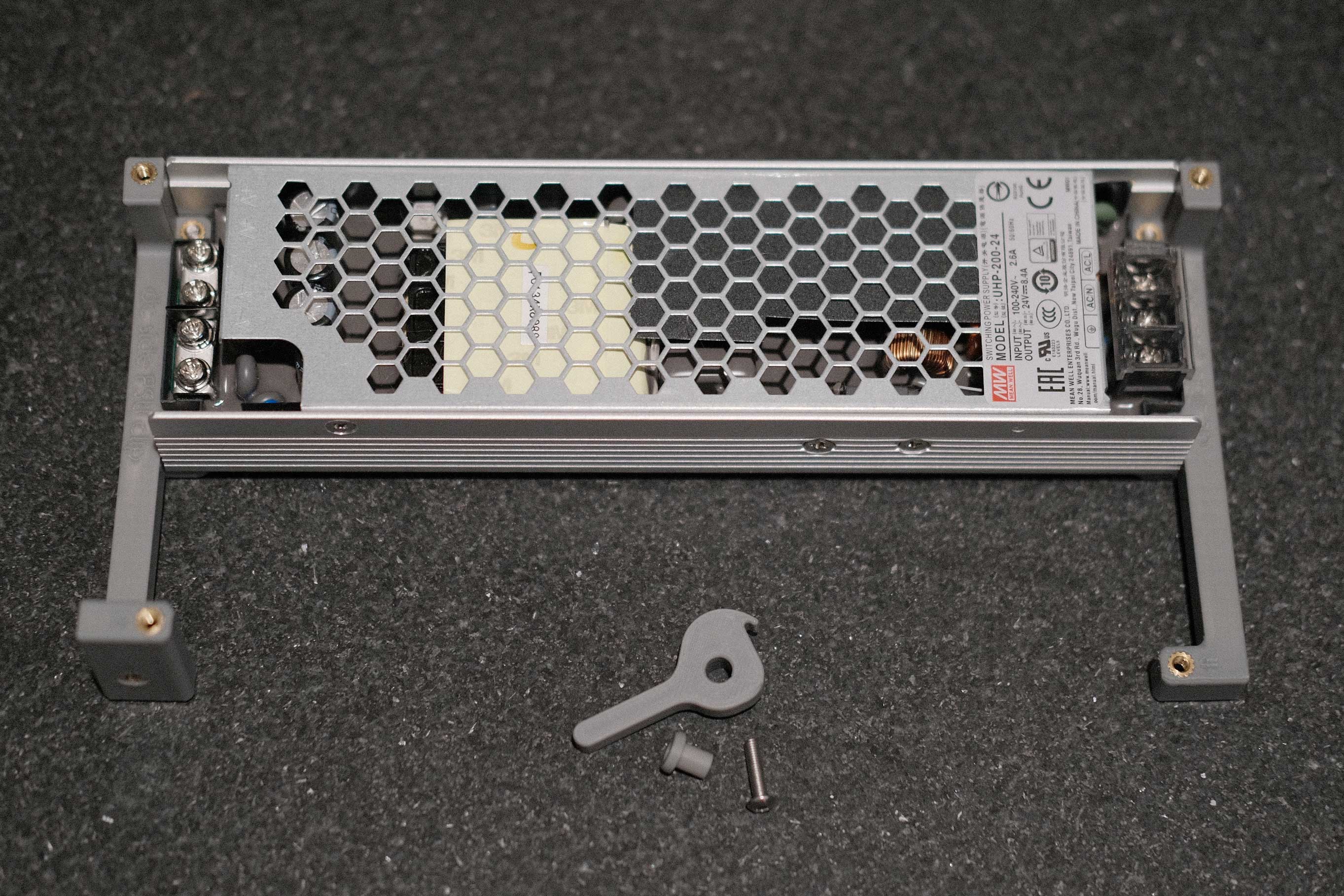 Electronics - 2
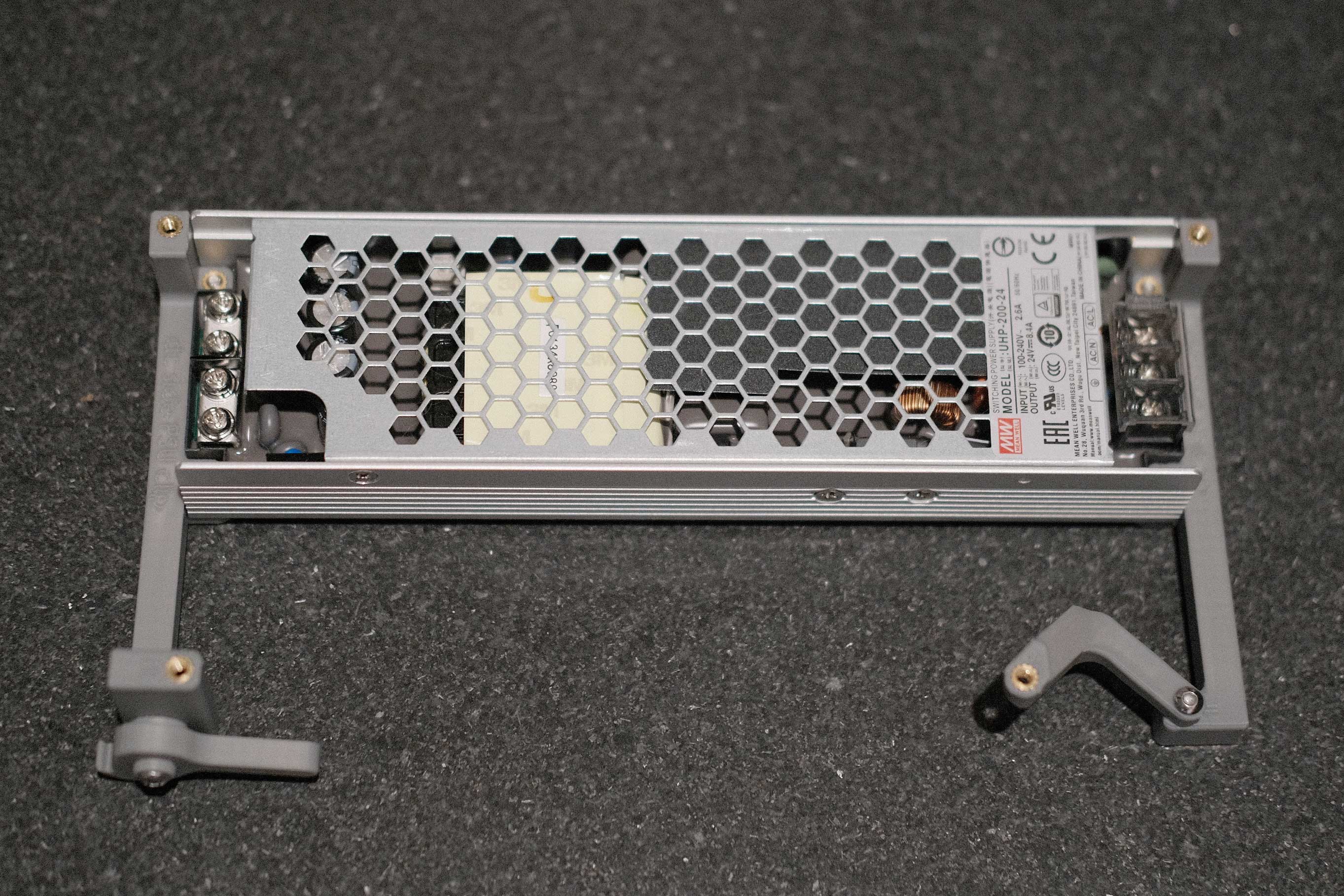
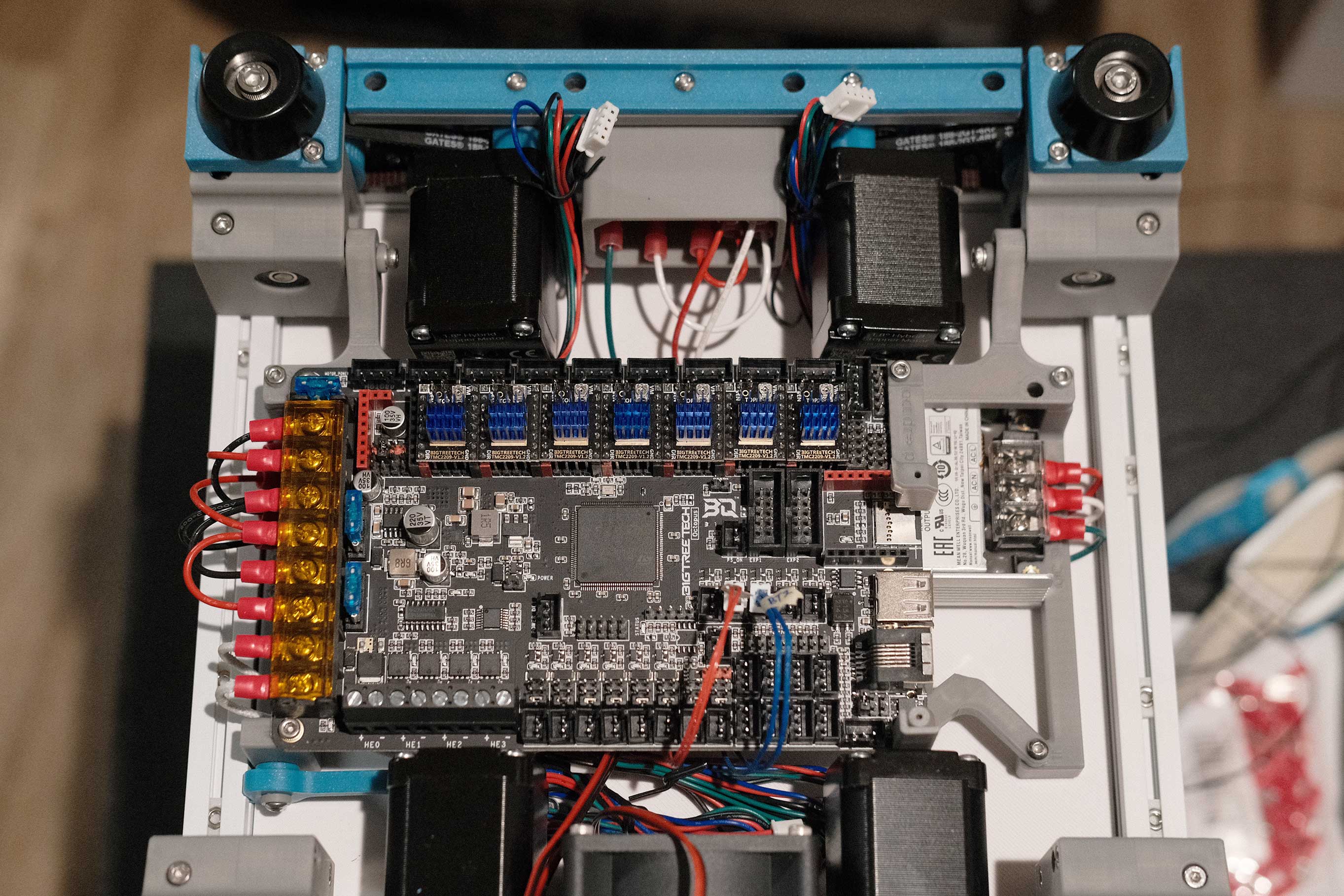
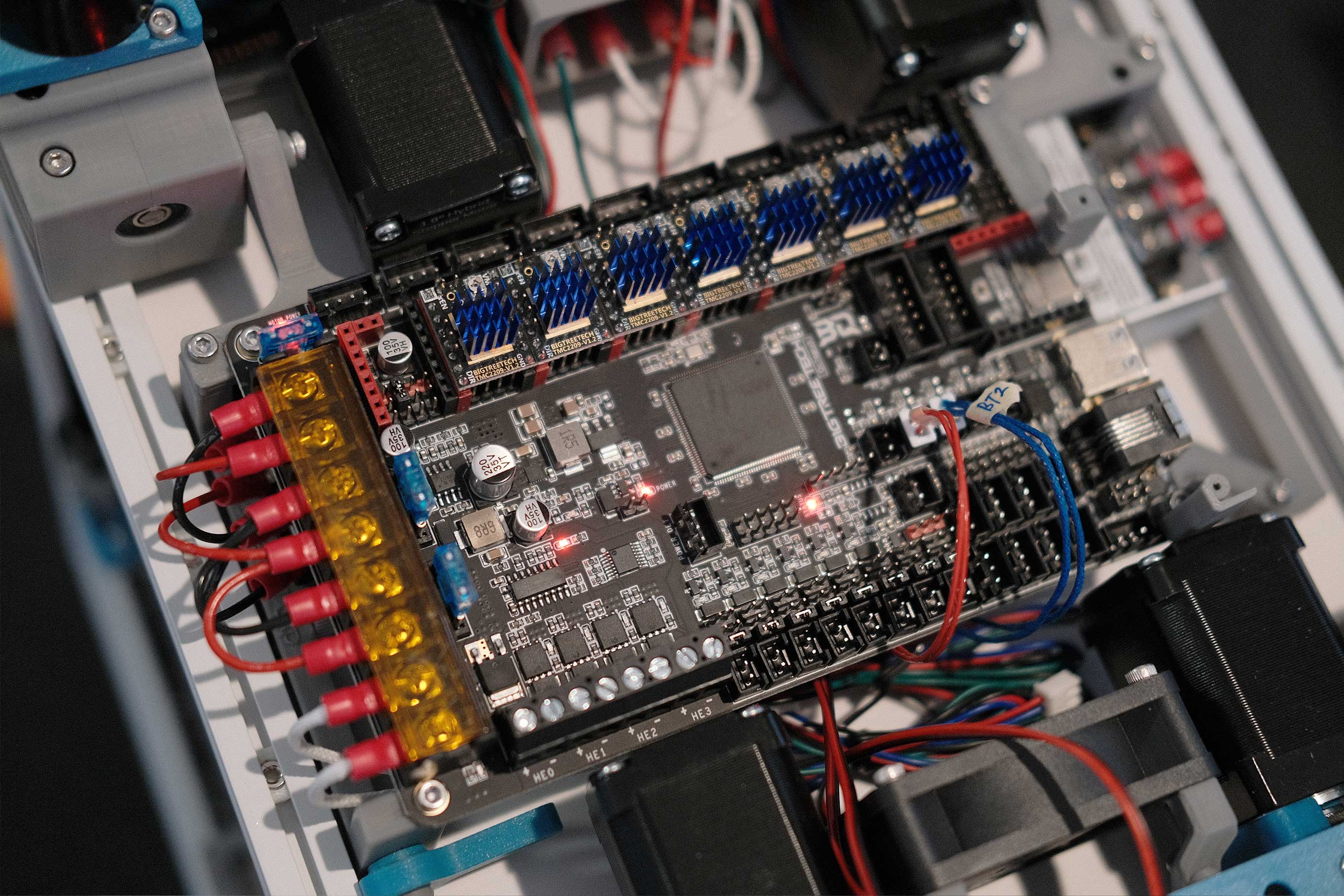
This boomerang-looking part is the elevated standoff to mount one corner of the Octopus.
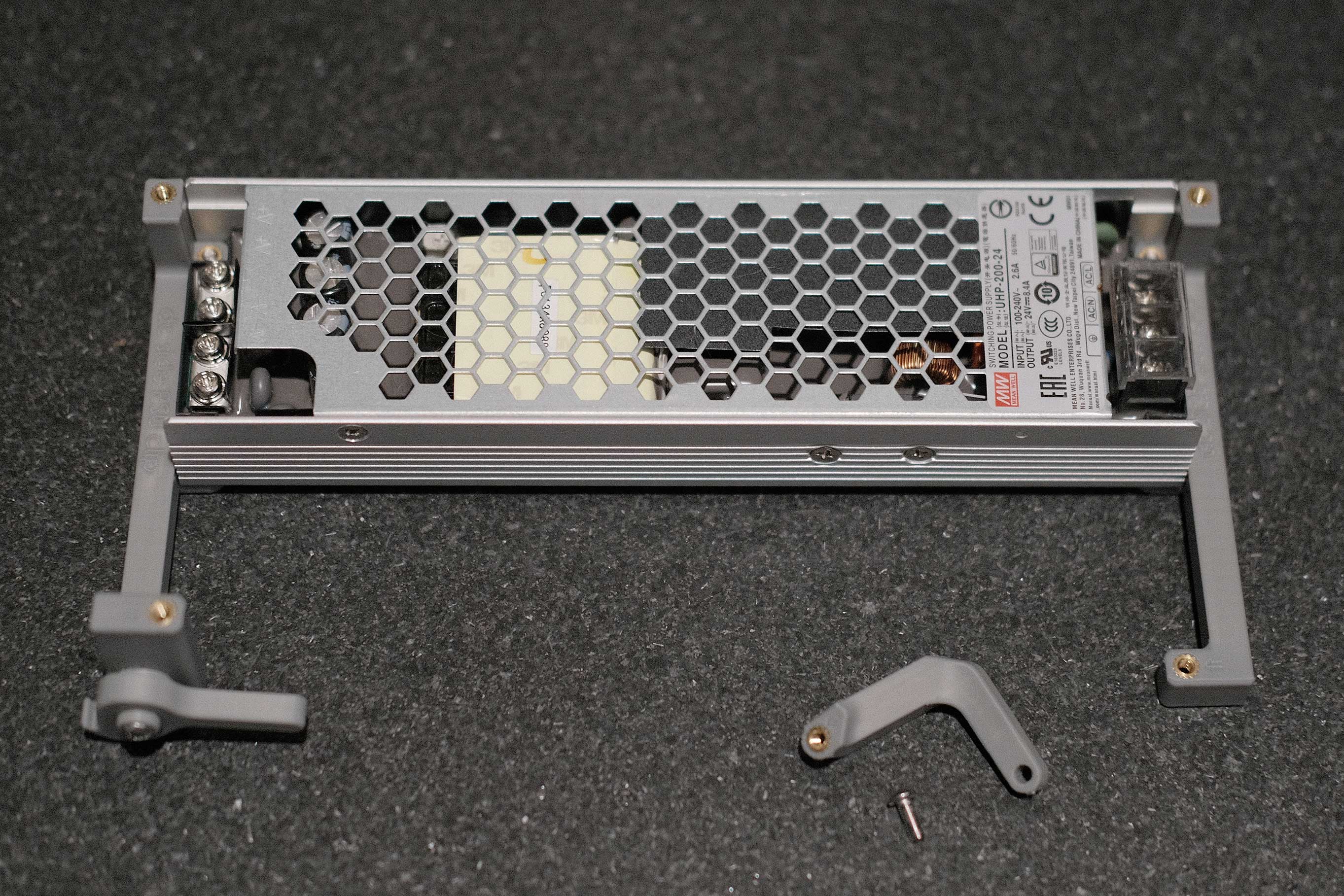 Electronics - 3
 Electronics - 4
The PSU mounts underneath the already installed hinge.
 Electronics - 5
The Octopus mounts on top of the PSU. The right side mounts of the Octopus have extra printed parts to secure the Pi with self-tapping screws.
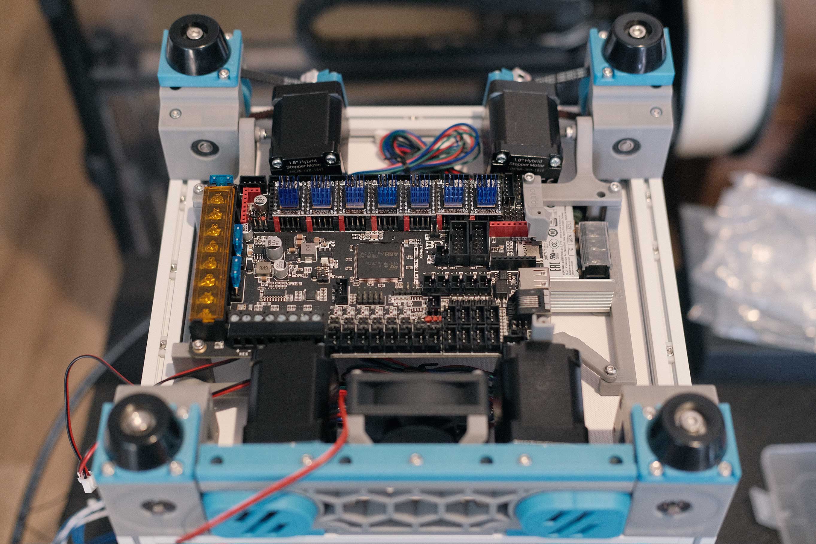 Electronics - 6
Wiring
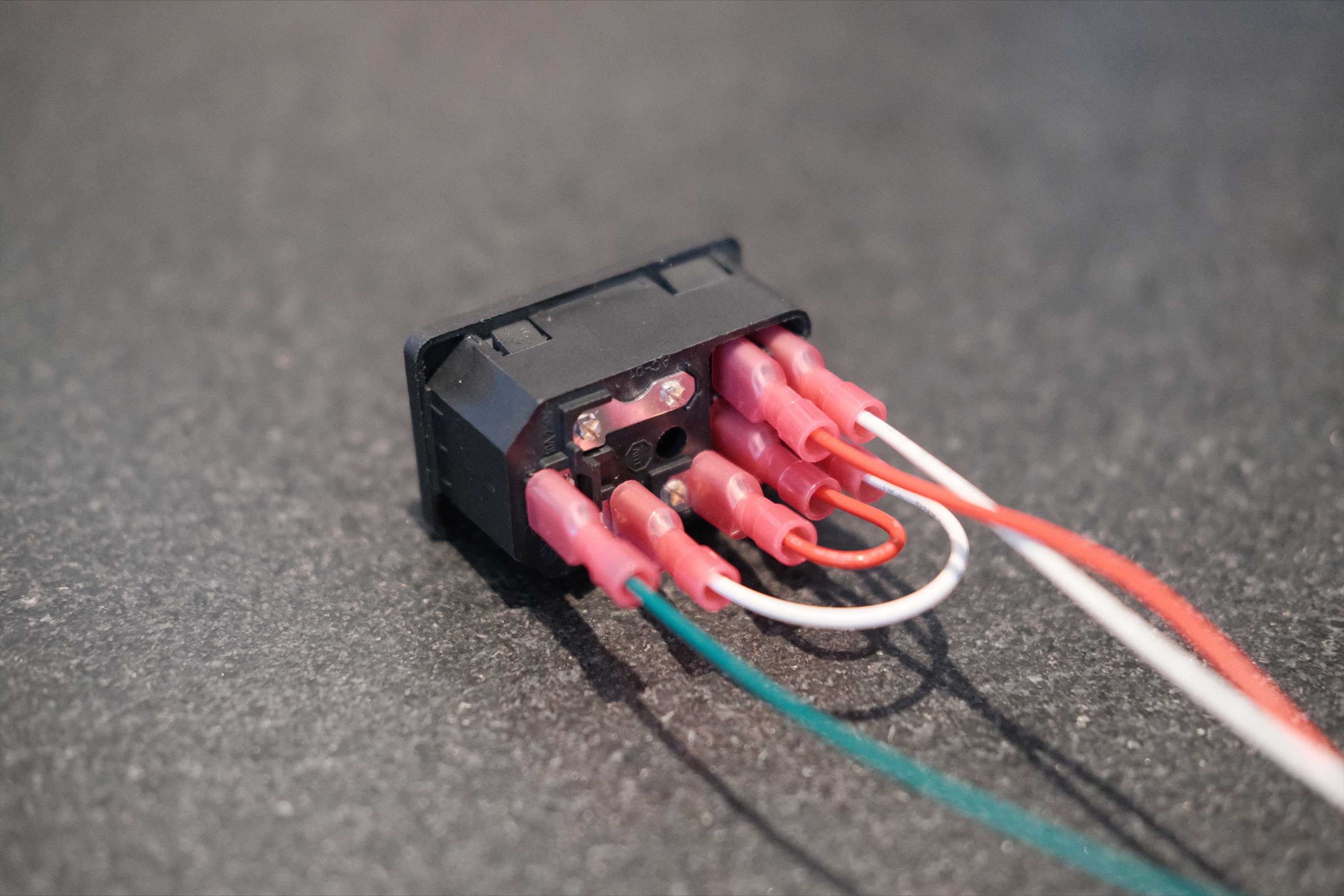 AC - 1
The mains wires are routed underneath the PSU, coming out on the right and into the AC side of the PSU.
 AC - 2
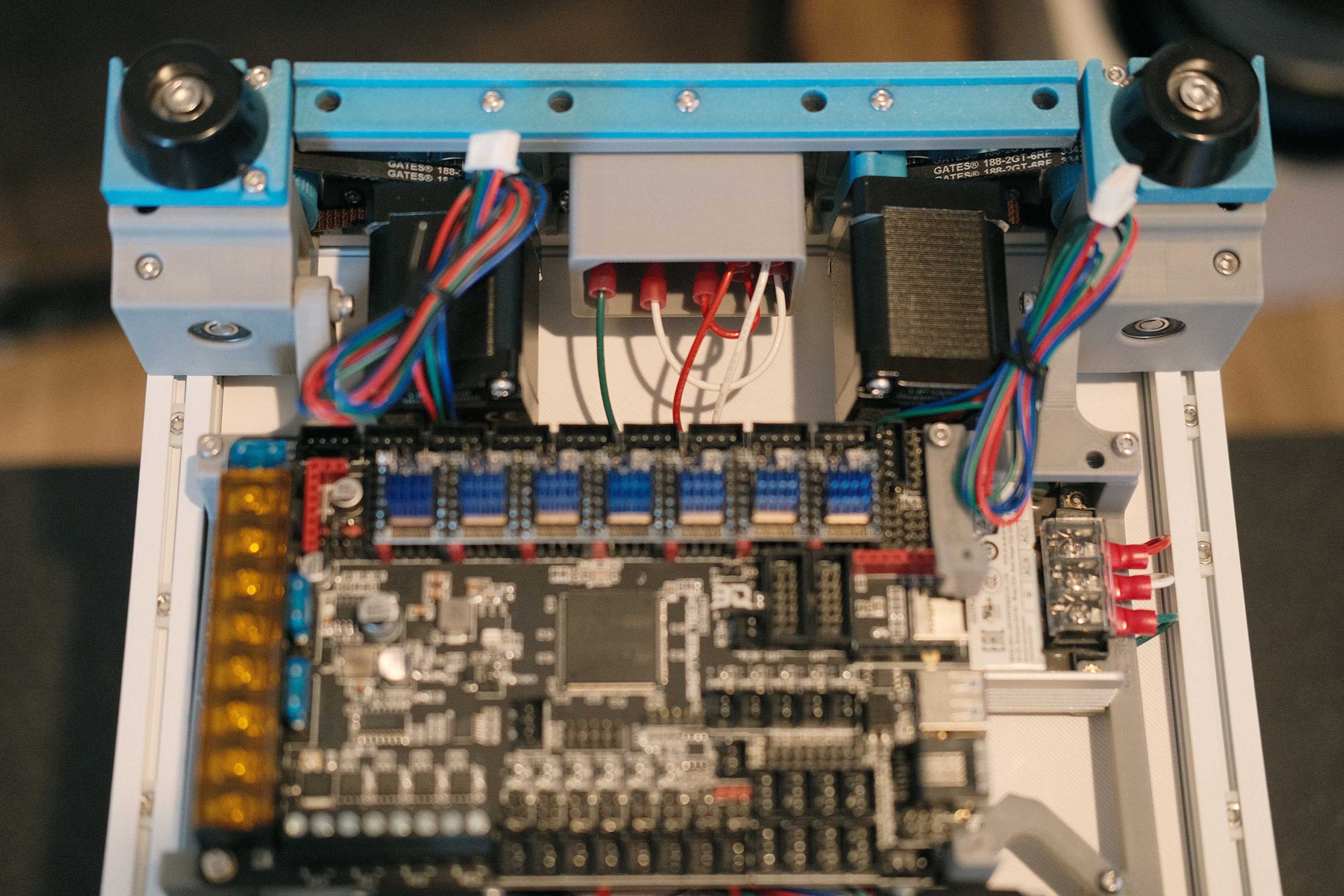
The bed wires (heater and two thermistors) are fed into the center hole.
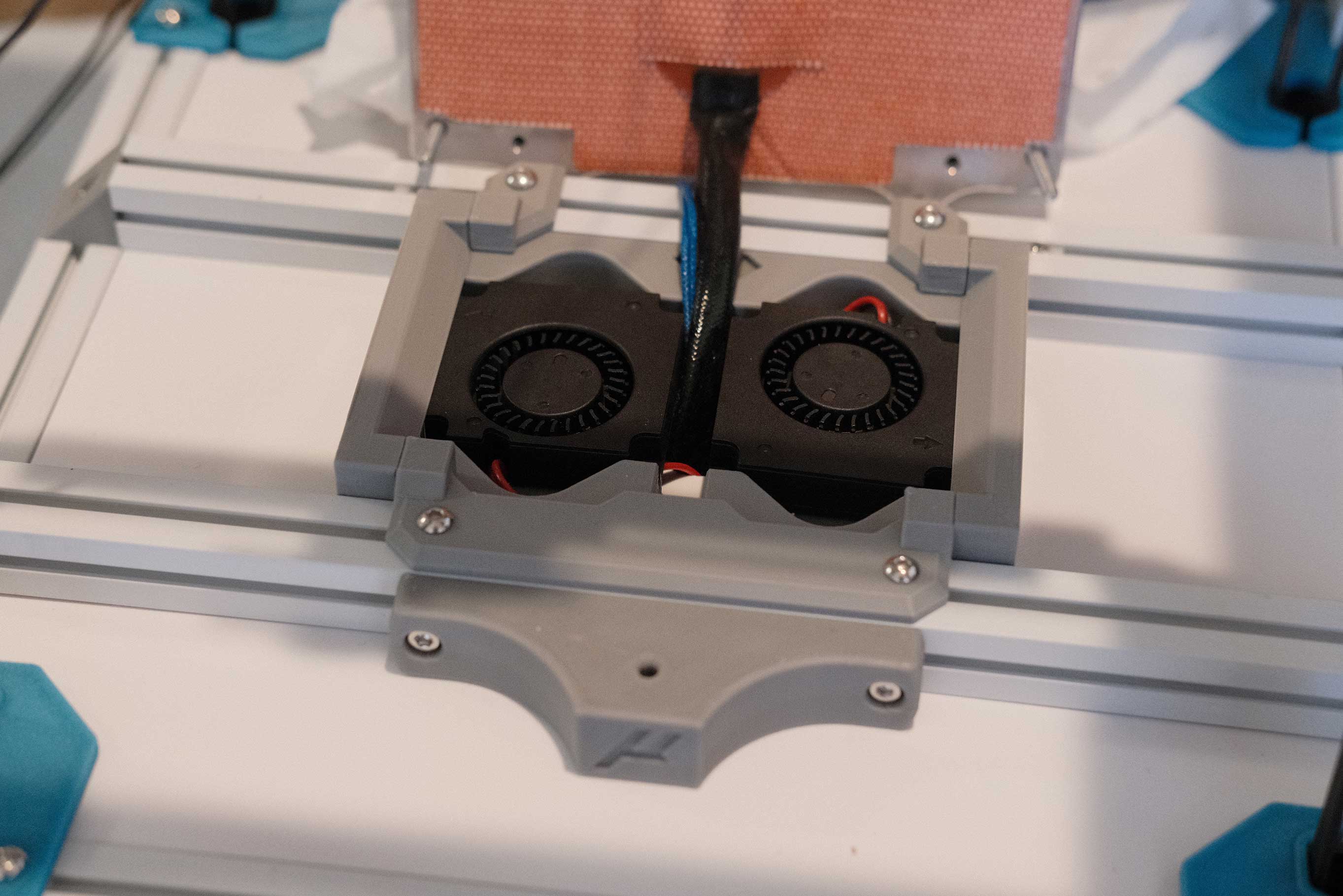 Bed - 1
So clean!
 Bed - 2
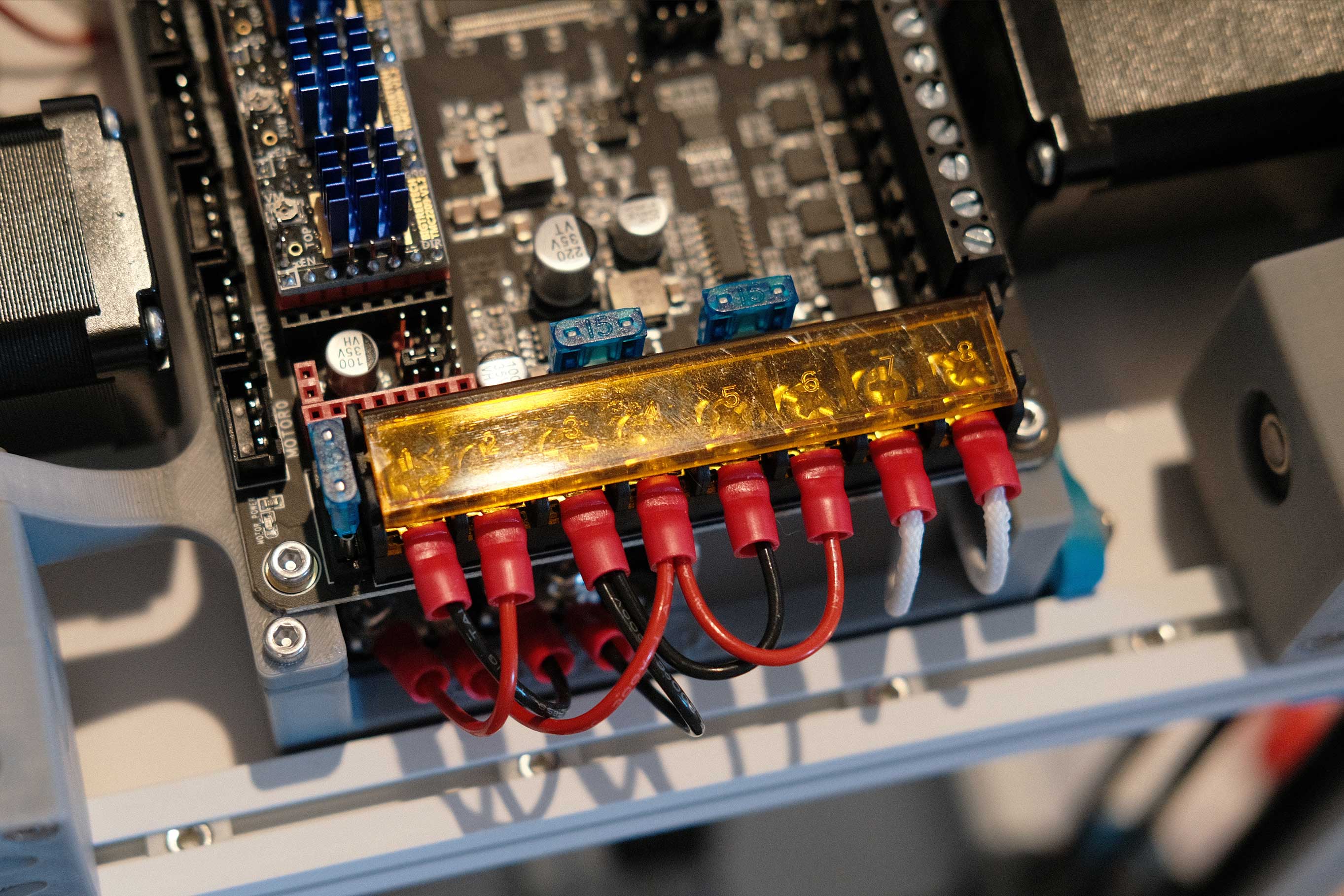
Bed heater wires (white) are installed on the lower left. The bed thermistors are installed in the center (red and blue).
 DC - 1
The DC side of the PSU are +/+/−/−, so make sure to keep proper polarity. And I’m jumpering from the second pair to the third pair on the Octopus. I’ve seen people stack spade connectors, but this looks cleaner to me.
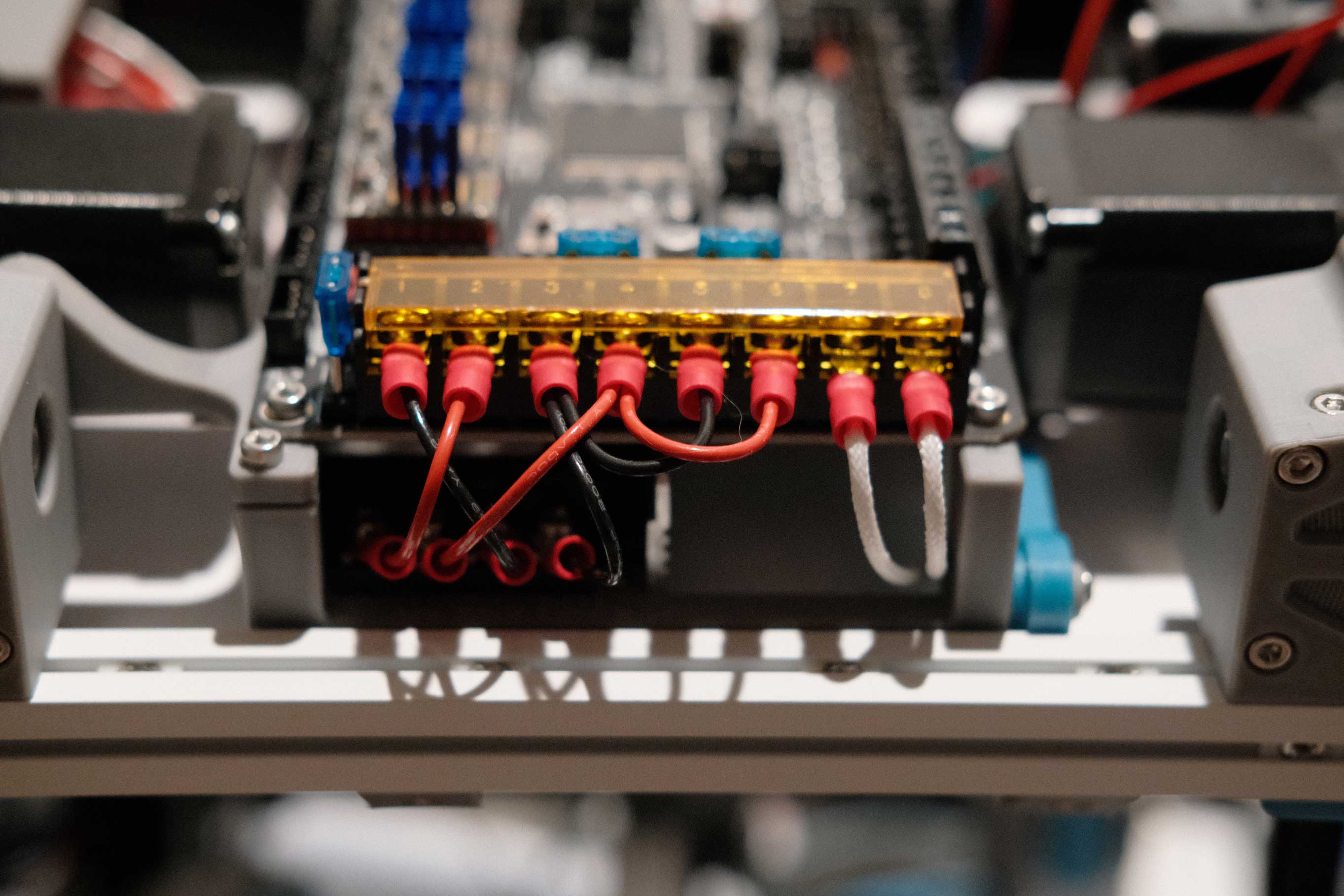 DC - 2
 DC - 3
A quick test now that AC/DC is all hooked up. We have lights!
 DC - 4
The four Z motors are fed up to the top of the hinge, cut to length, and re-crimped.
 Z Motors - 1
Mini Afterburner (Revisited)
Eyeballed the wire lengths so that the connectors all sit behind the extruder motor. On the far right, you can see the 4 tiny wires of the Delta hotend fan spliced to normal guage wires and split to two 2-pin connectors.
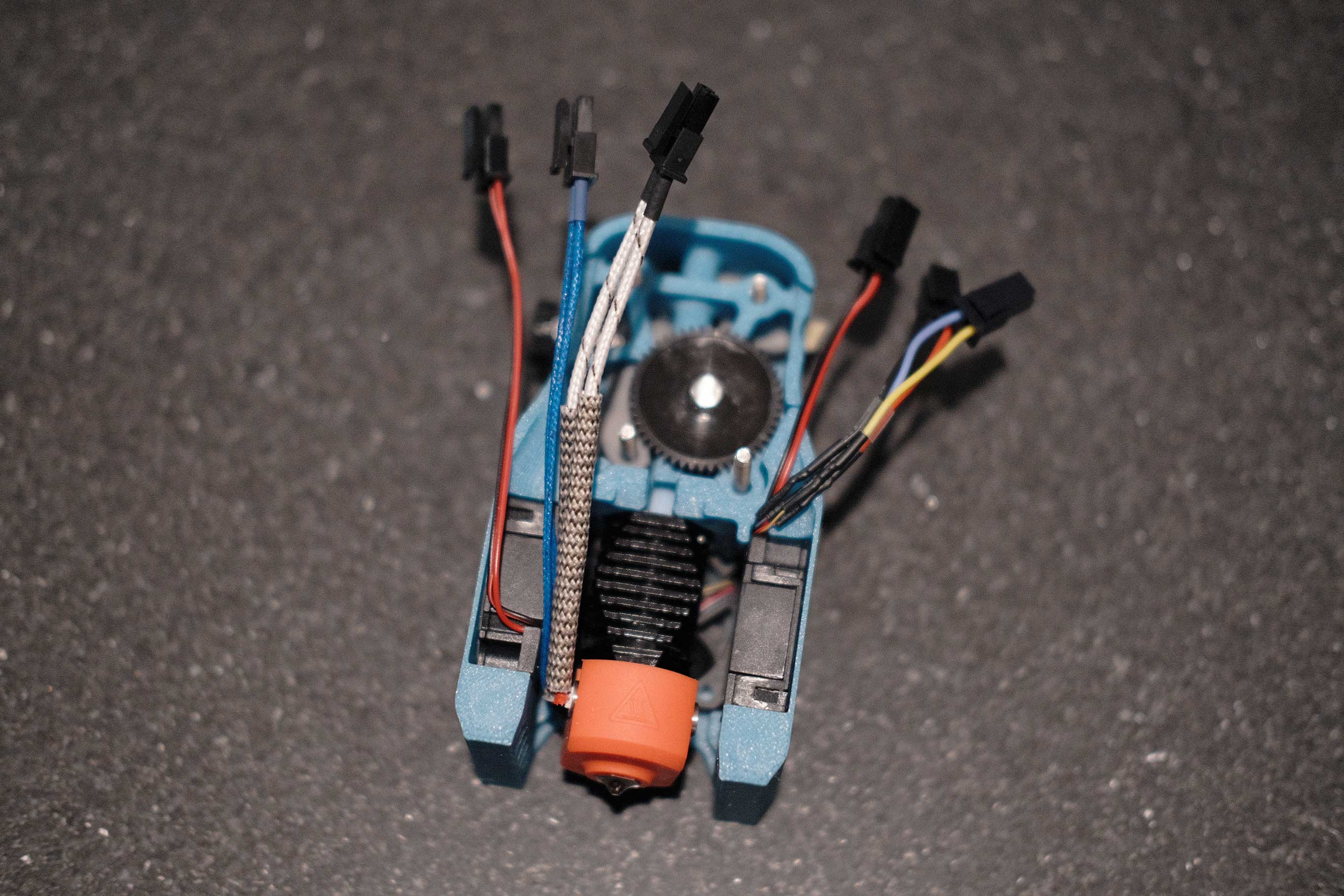 Mini Afterburner - 1
It’s a lot of connectors with nowhere to hide them.
 Mini Afterburner - 2
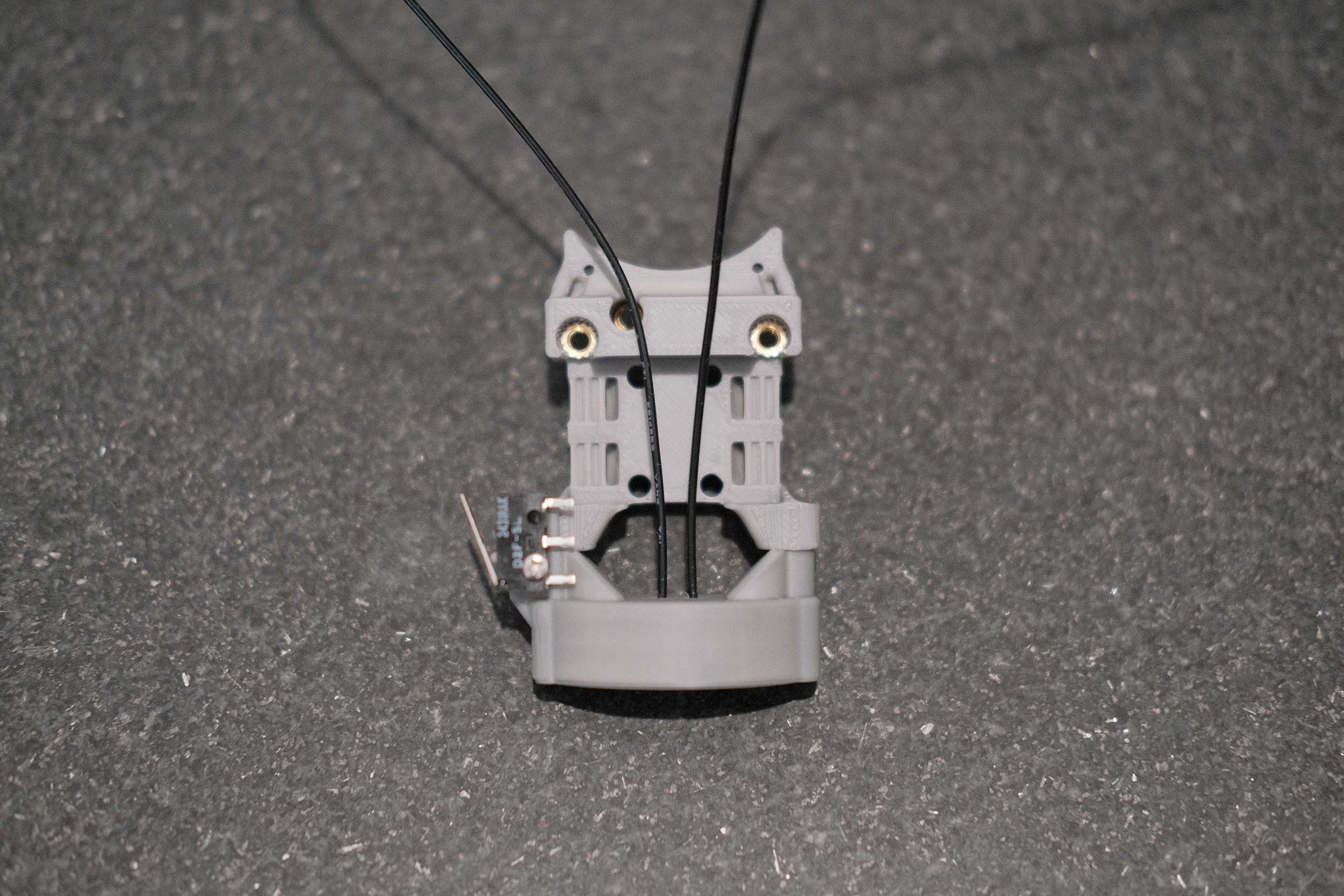
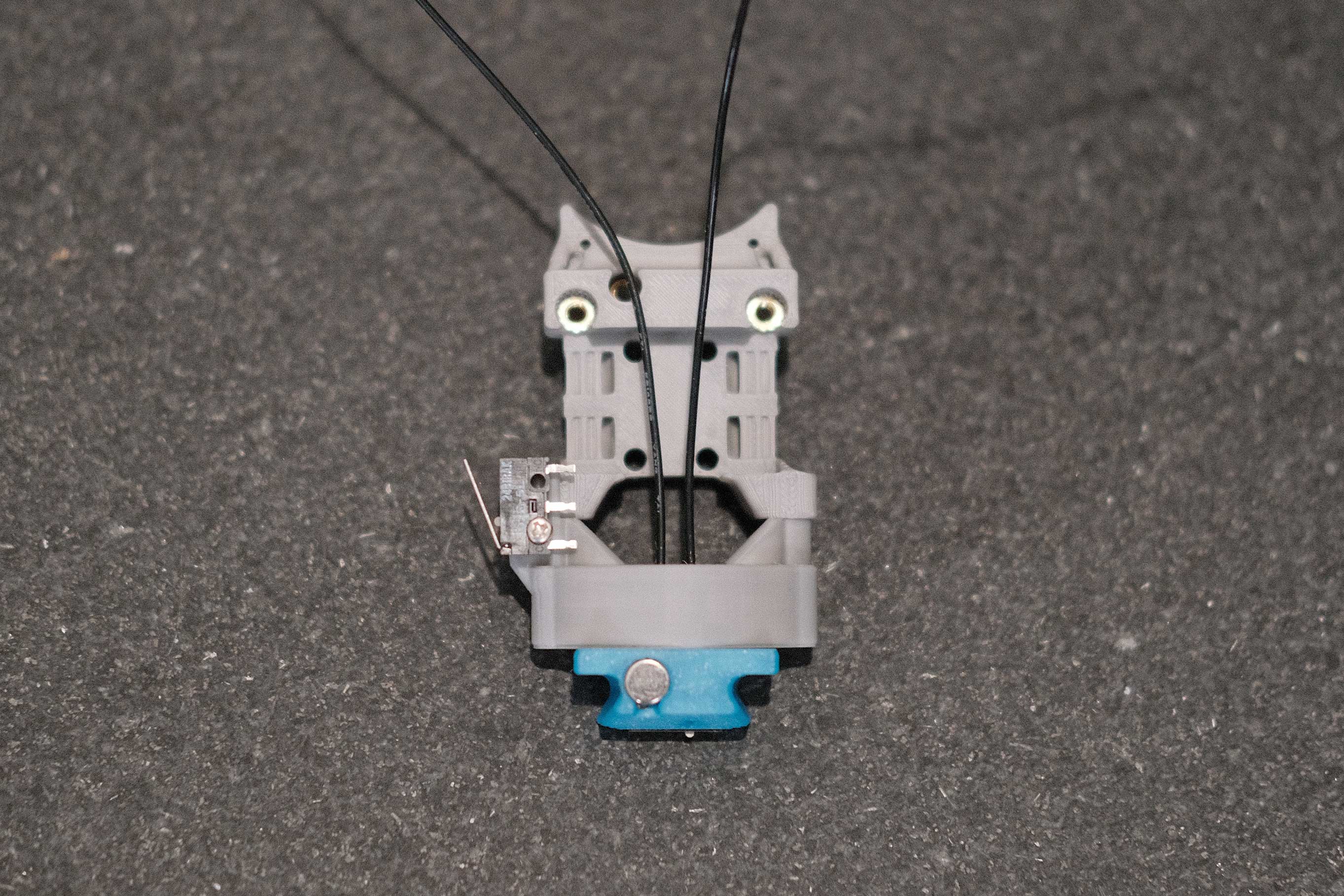
This is a rear shot of the X carriage mount to show how I routed the X limit switch and probe wires. X limit switch feeds through the center hole and to the left to join the wires on that side, while the probe switch feeds to the right and joins the wires on the opposite side.
 Mini Afterburner - 3
With this many Microfit connectors, I really should invest in a de-pinning tool.
 Mini Afterburner - 4
The rear side of the mini Afterburner assembly has two zip tie points. Arrange the wire-bundles accordingly, and secure them with zip ties.
 Mini Afterburner - 5
I am trying to hide the extruder motor’s 4-pin Microfit connector behind the wires. Lol.
 Mini Afterburner - 6
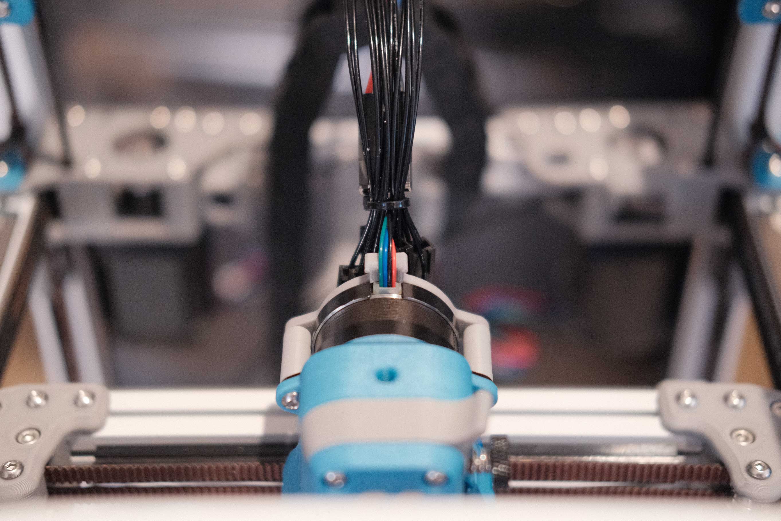
Run the wires through the umbilical sheathing and the outer part of the cable gland. Here you can see how full the cable gland inlet is. I don’t think I could fit even one more FEP wire. It’s pretty tough to keep all the wires untangled.
 Mini Afterburner - 7
 Mini Afterburner - 8
This will do until I get the fancy two-tone woven sheathing in August.
 Mini Afterburner - 9
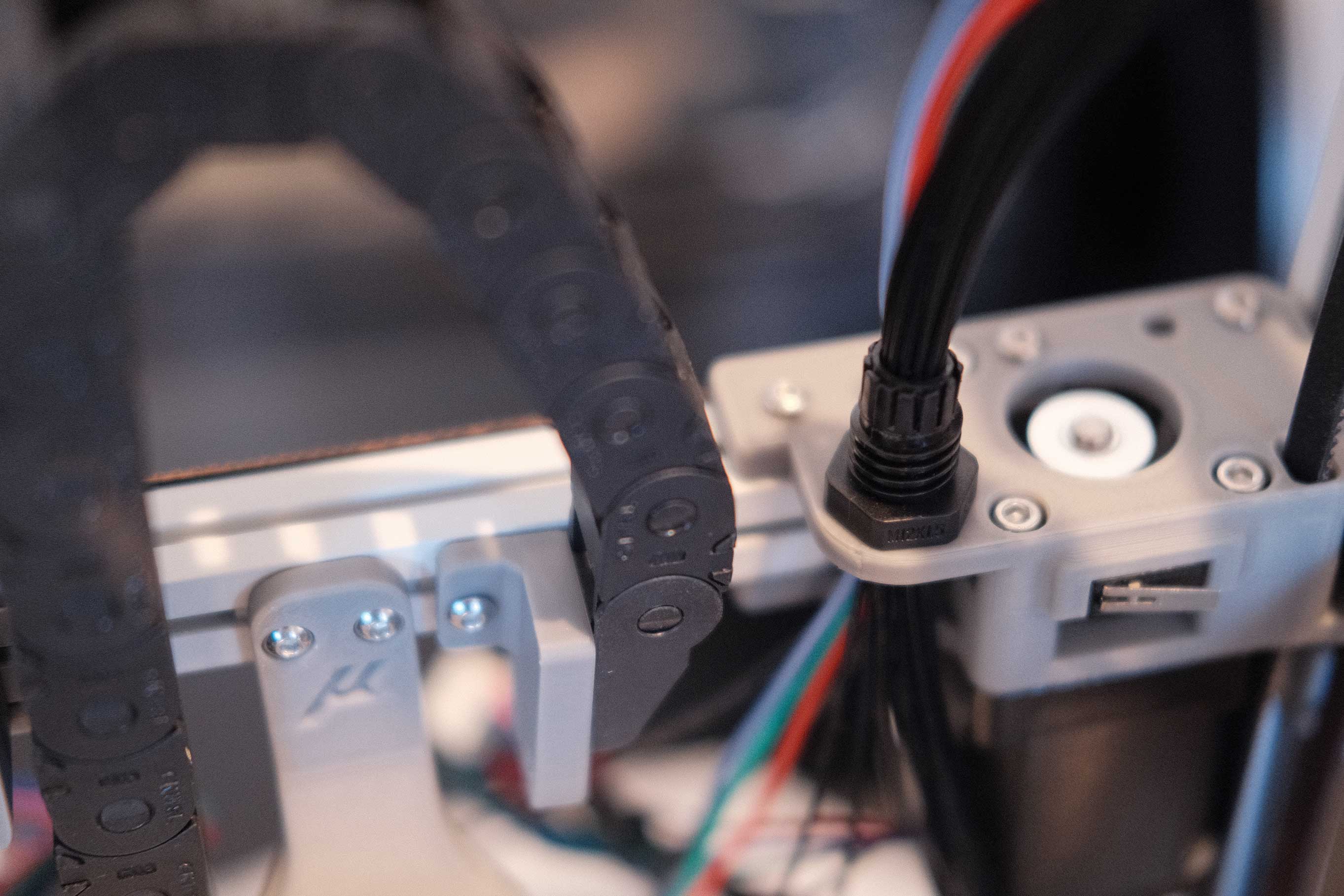
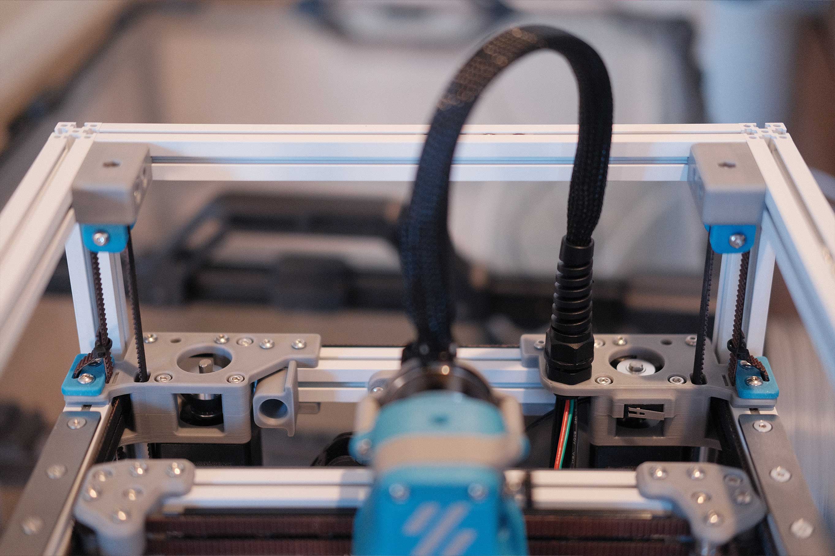
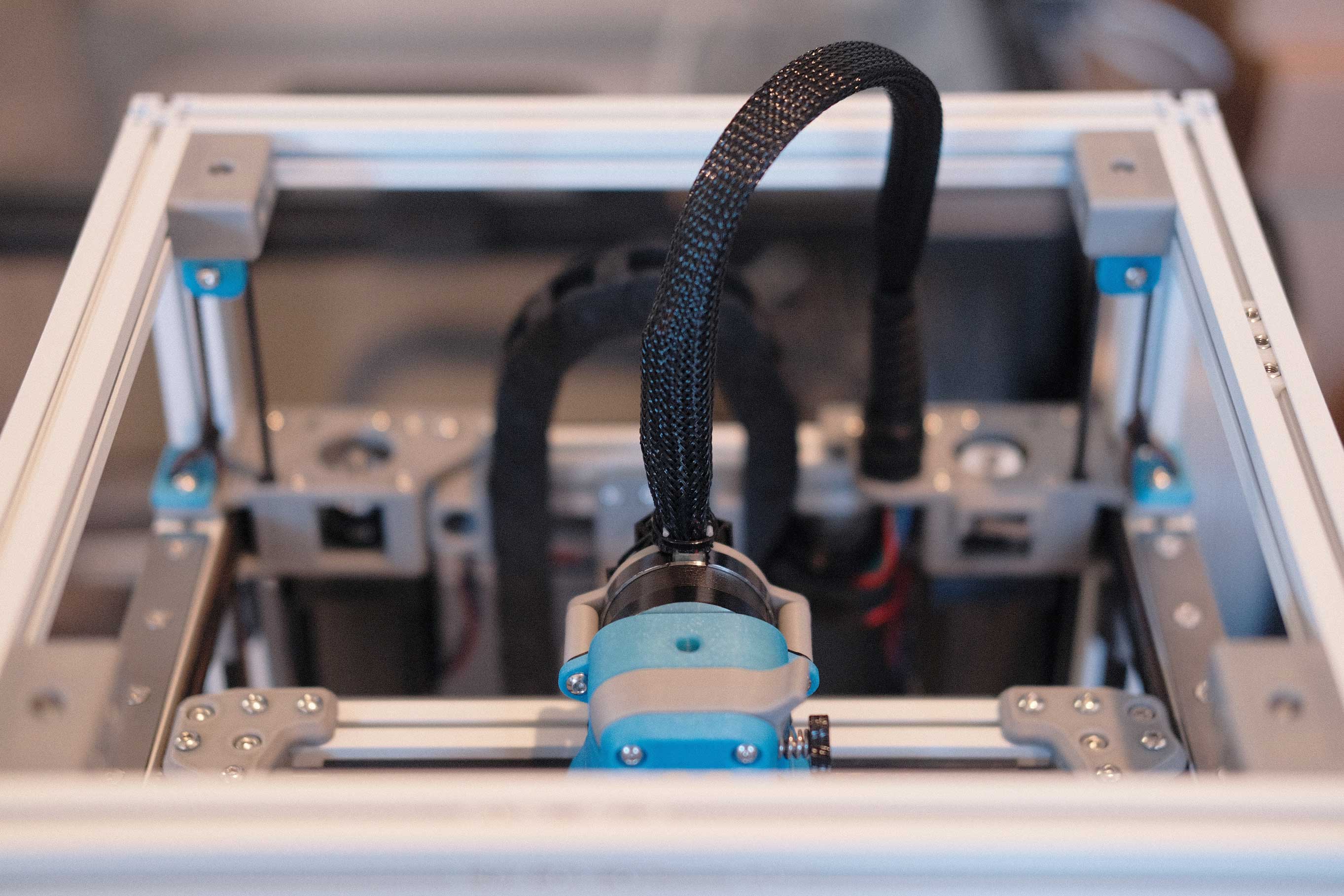
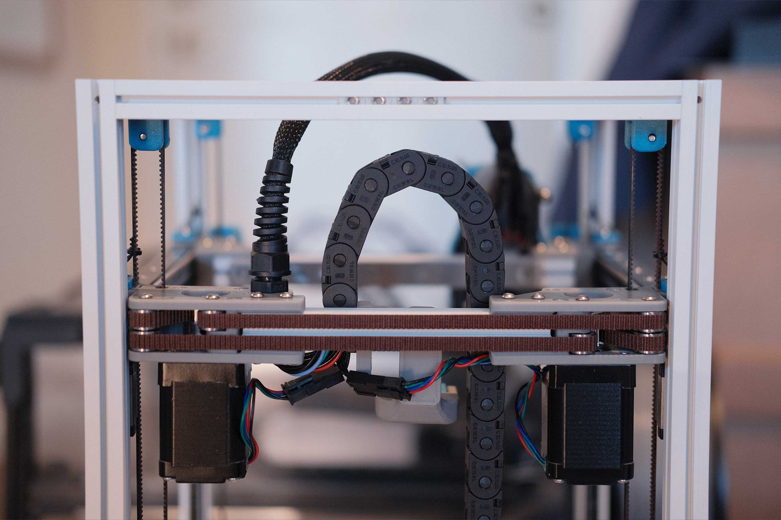
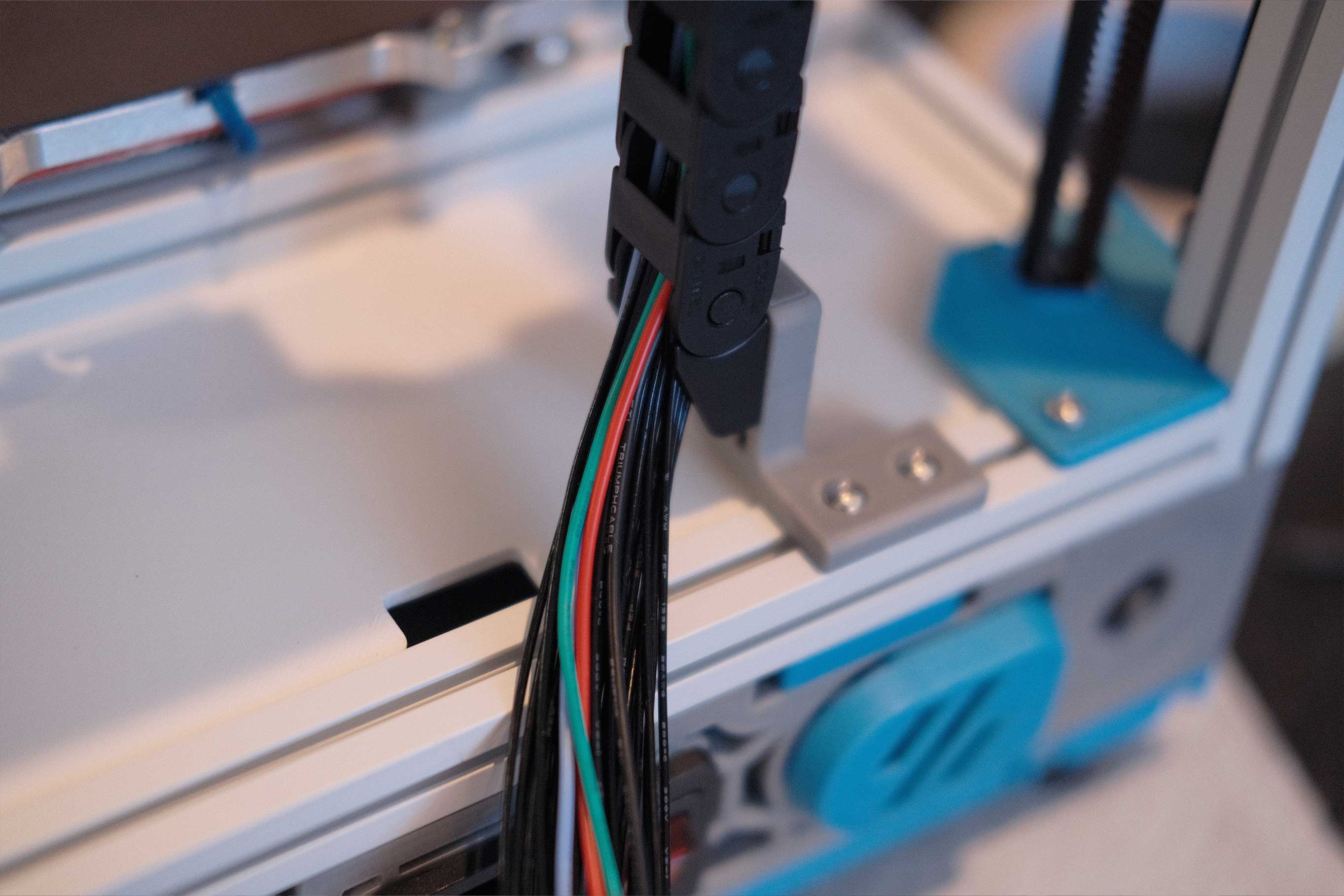
Umbilical/Cable Chain
I might have accidentally forgot to take photos while maneuvering wires through the cable chain. It’s leftover 10x11 chains from my Trident build with redesigned mounting parts to fit the 3-hole screw pattern common to generic brands.
Also, the A/B motor wires were too short to actually reach the controller board, so I opted to cut them here before the chain to extend them.
 Umbilical/Cable Chain - 1
I regret not using the same black FEP for the extruder motor. It’s the only colored wires in the bundle.
 Umbilical/Cable Chain - 2
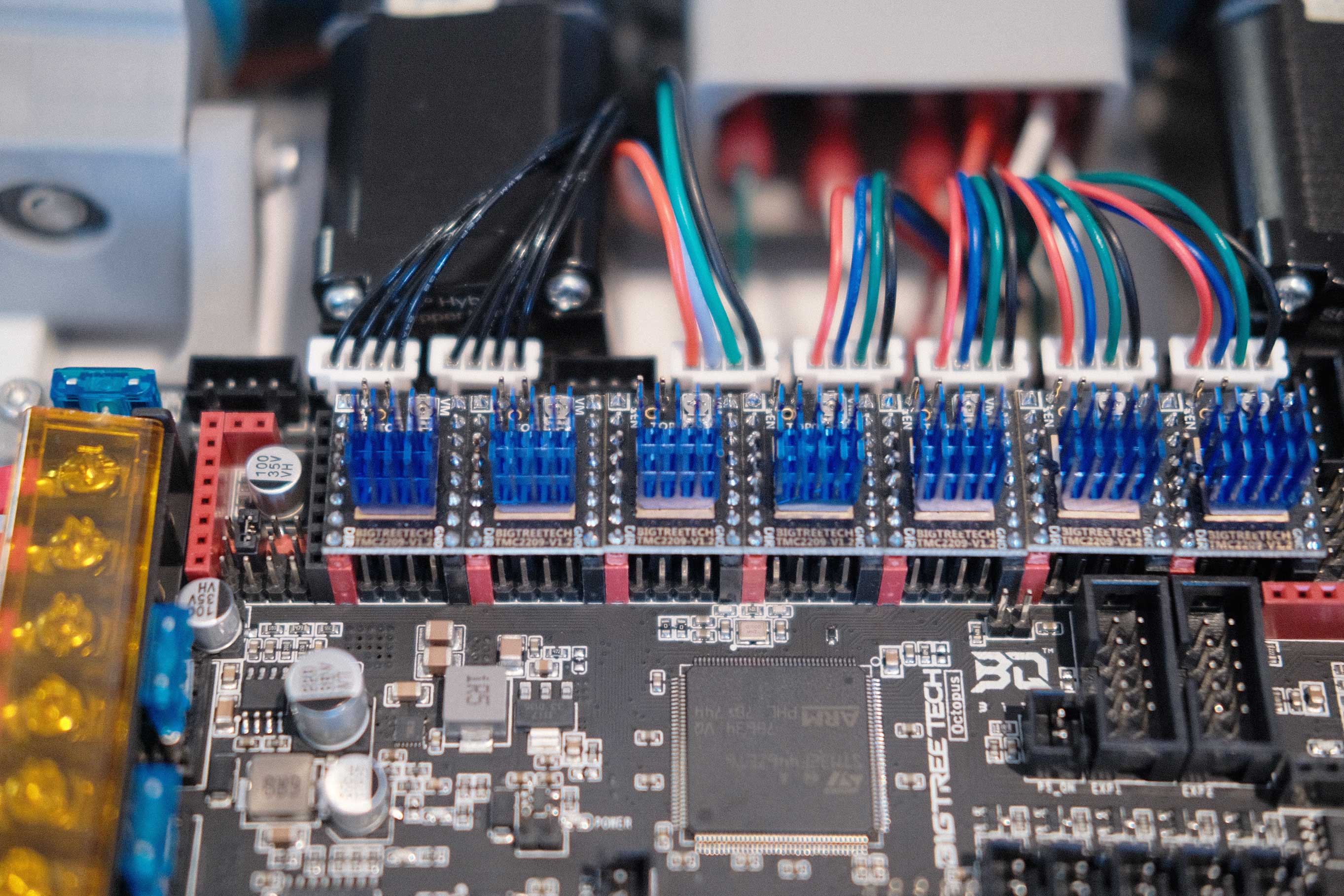
Wiring
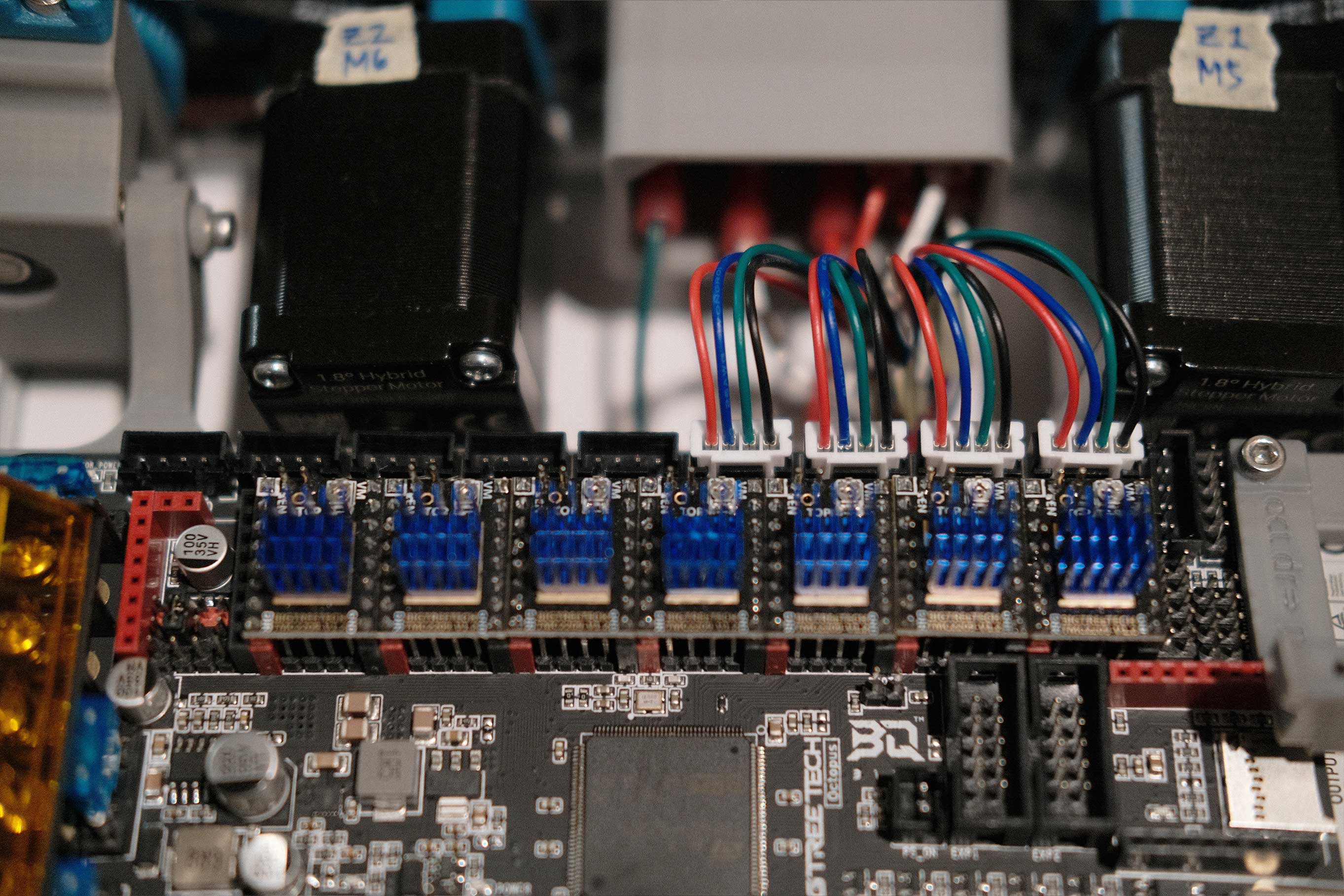
Final stepper motors connected: blank, A, B, blank, E, Z0, Z1, Z2, Z3.
 A/B & Extruder Motors - 1
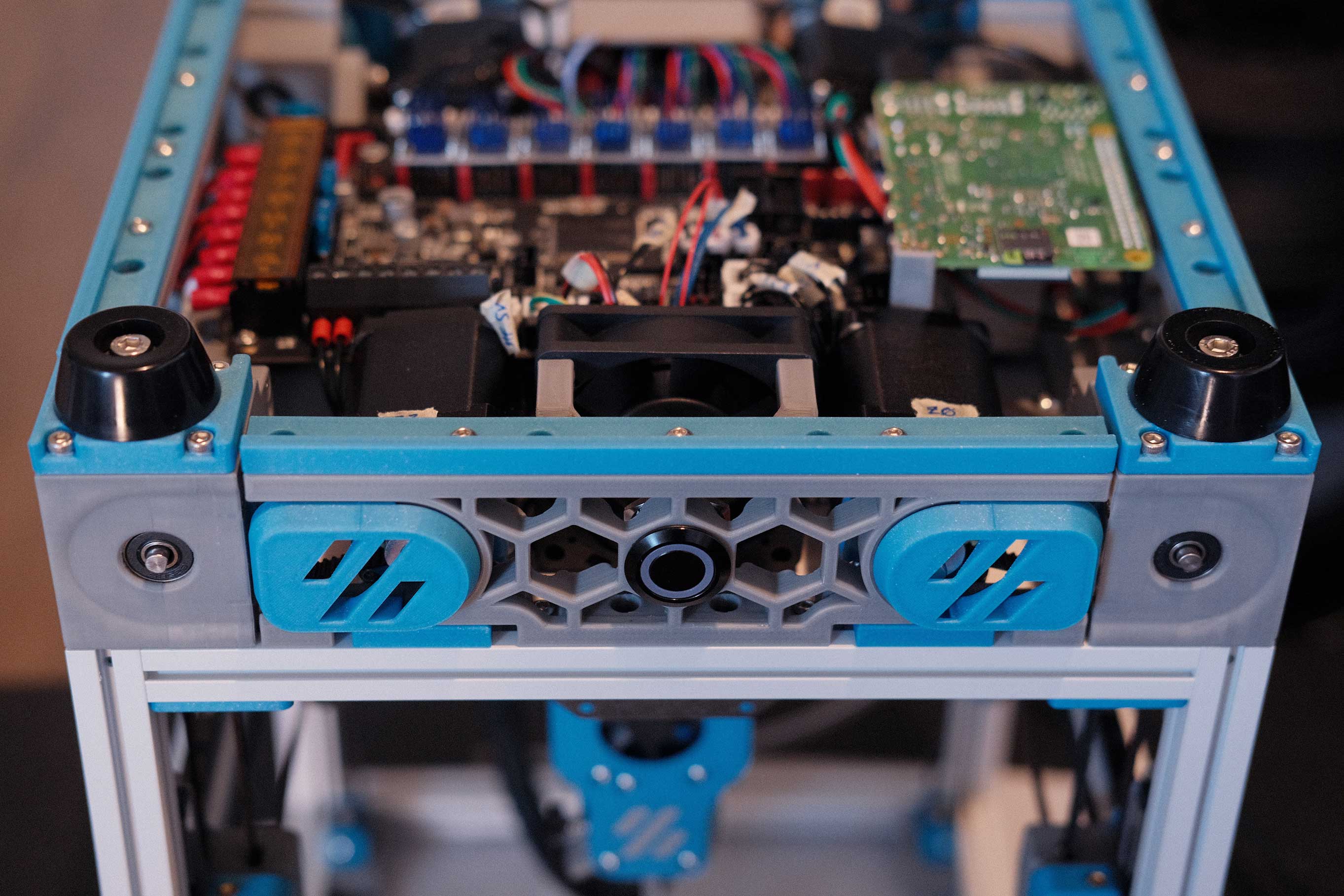
Here’s a shot of the electronics before I stack the Raspberry Pi.
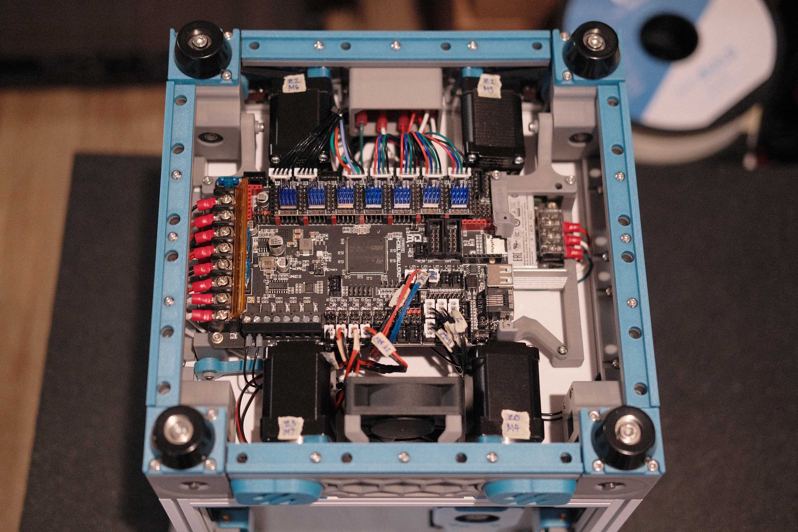 A/B & Extruder Motors - 1
Powering the Raspberry Pi with 2x 5V and GND from the Octopus to the GPIO header.
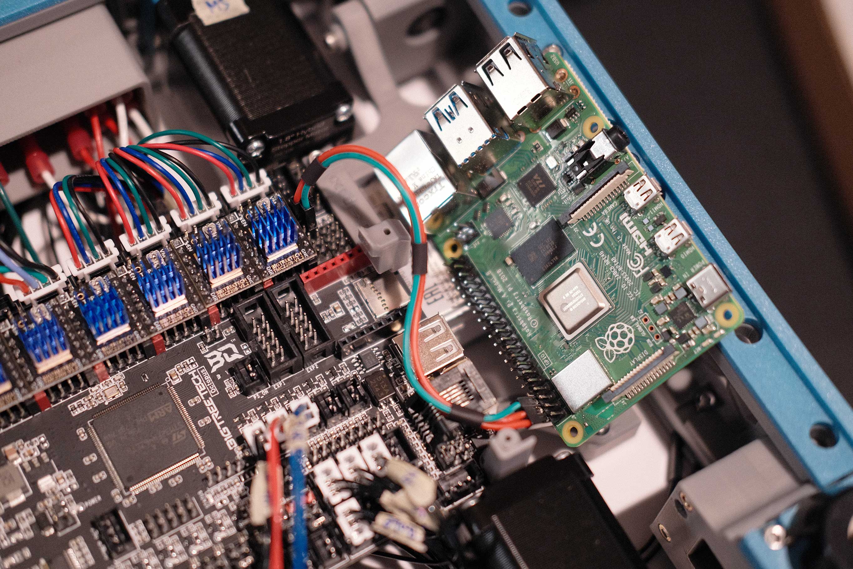 Raspberry Pi - 1
USB-C for data connection. Then flip the Rasbperry Pi over and secure with self-tapping screws.
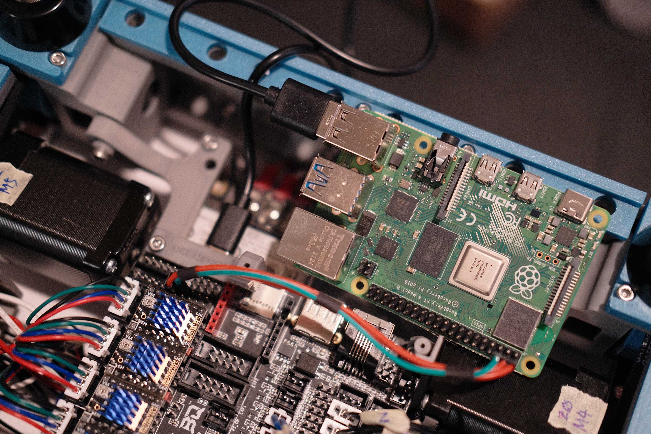 Raspberry Pi - 2
Wiring complete!
 Wiring - 1
Powering it on that first time always makes me so nervous, but all the magic smoke stayed inside and we have lights!
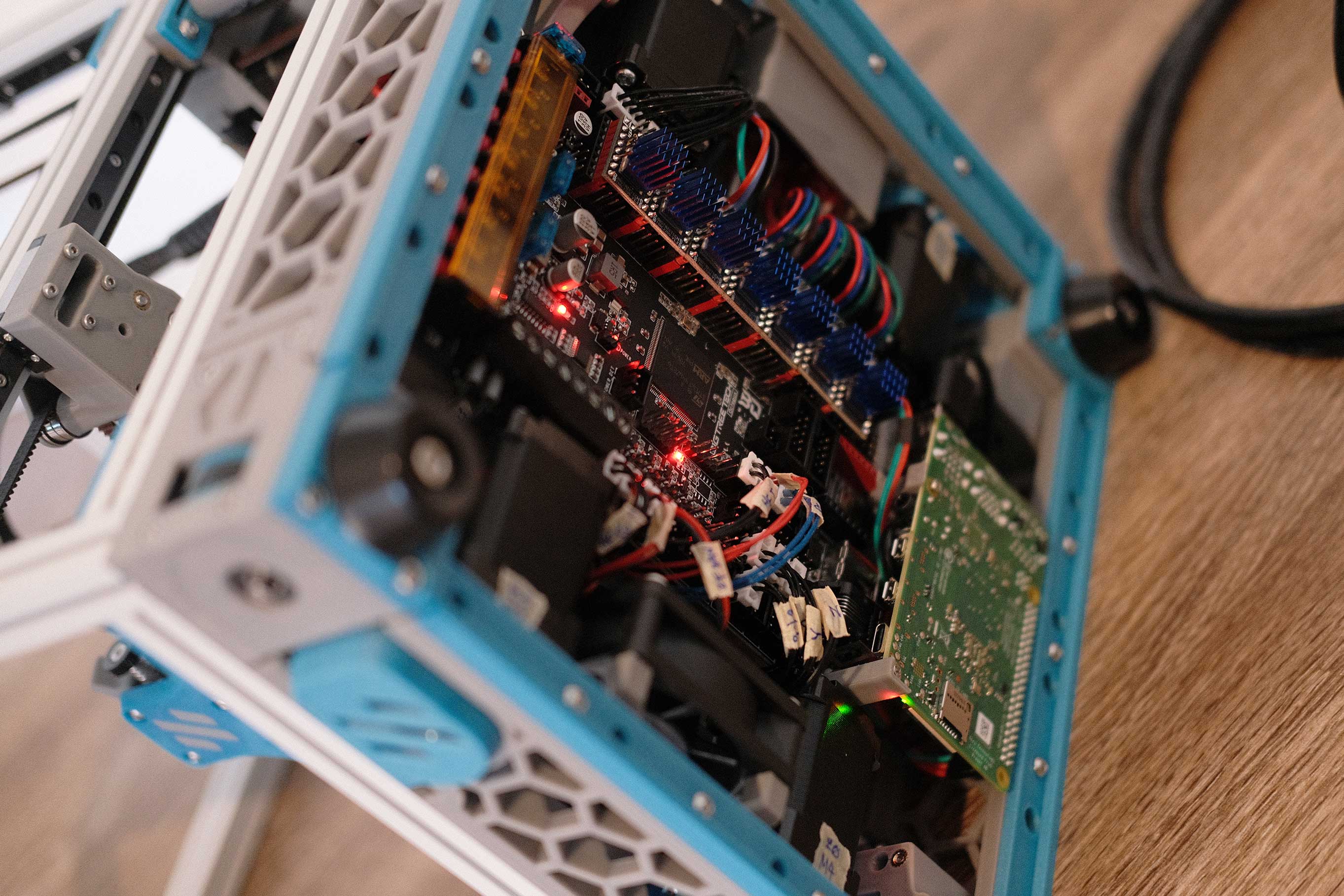 Wiring - 2
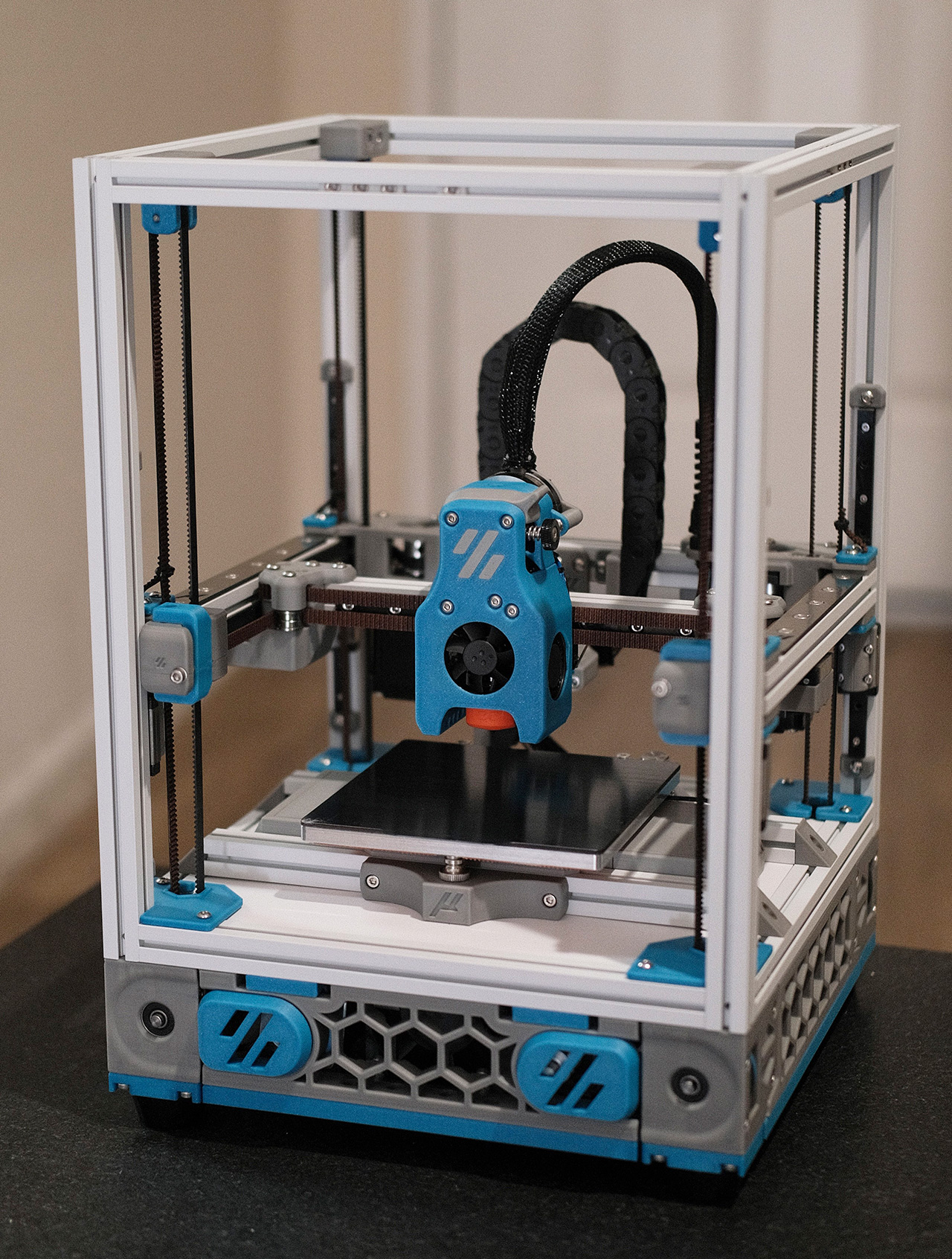
Initial Build Complete
*Tears up
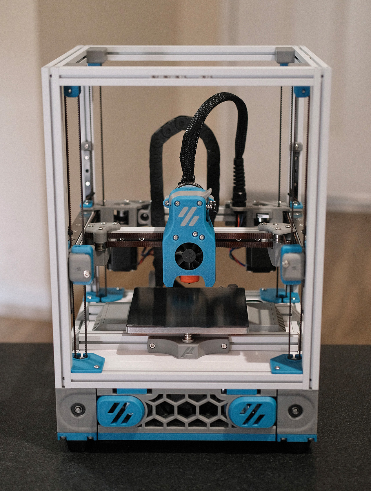 Initial Build Complete - 1
 Initial Build Complete - 2
 Initial Build Complete - 2
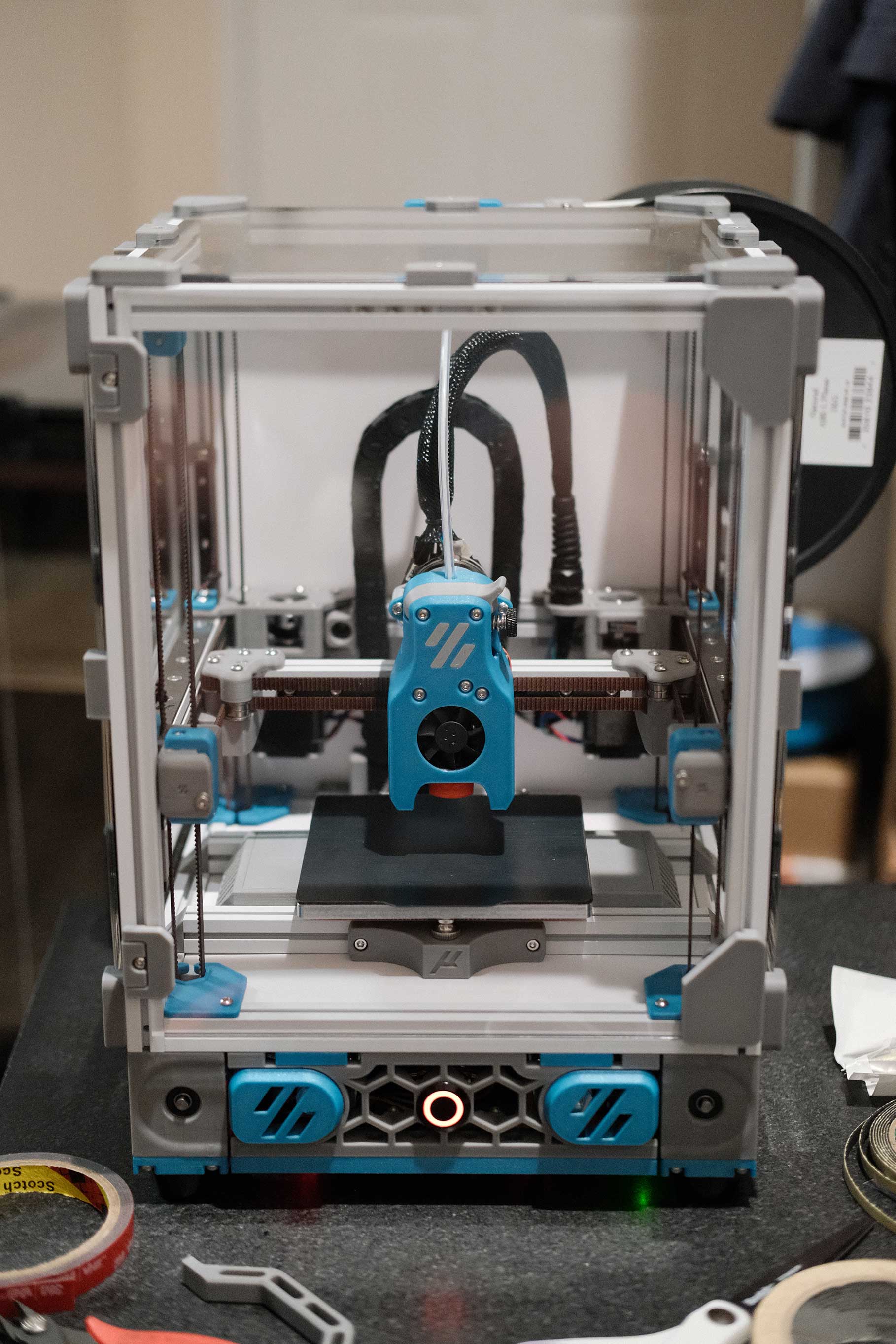
Neopixel Front Button
The Micron is headless and neopixel-less up to this point. To bring back some utility, I added a Chromatek 19mm Momentary Push Button. The built-in neopixel will work as a status indicator and the button will cycle through the same preheat macros that my Trident has (60C for PLA → 110C for ABS → 0C for idle).
The wiring is not complicated, but to make it fit, I had to give up the included harness and extend the electronics fan arms 10mm.
![]() Neopixel Front Button - 1
Neopixel Front Button - 1
![]() Neopixel Front Button - 2
Neopixel Front Button - 2
You have the same 3 wires (5V in, data in, and ground) that Stealthburner neopixels have, and you have the same 2 wires (NC and ground) that limit switches have.
![]() Neopixel Front Button - 3
Neopixel Front Button - 3
![]() Neopixel Front Button - 4
Neopixel Front Button - 4
I had to make sure to bend the spades a bit extra so that the wires clear the spinning fan.
![]() Neopixel Front Button - 5
Neopixel Front Button - 5
Here’s how I positioned the wires.
![]() Neopixel Front Button - 6
Neopixel Front Button - 6
My mini arc reactor lives.
![]() Neopixel Front Button - 7
Neopixel Front Button - 7
![]() Neopixel Front Button - 8
Neopixel Front Button - 8
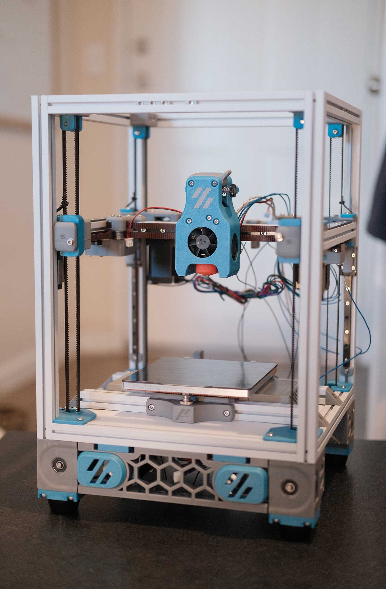
Panels
I lined the rear and top panels with 1mm foam tape and they worked perfectly fine with the stock clips, but I lined the side panels with 3mm foam tape to provide clearance for the linear rail carriages, and these required making the stock clips 2mm deeper. I also flipped the front door 180° and opted to not VHB the handle just yet. Front door has no foam tape because it would affect the action of the hinge.
Fully enclosed and printing ABS!
 Panels - 1
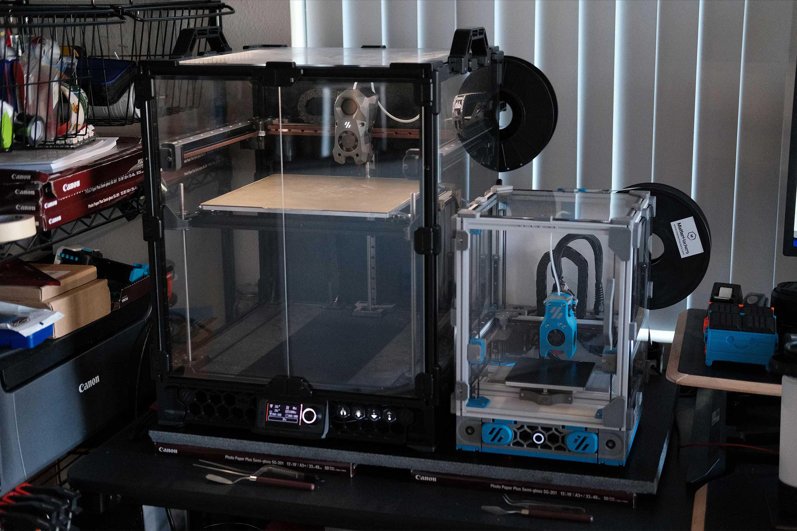
Comparison to 300mm Trident
And here it is next to the 300mm Trident.
 Trident and Micron - 1
Neopixel Sticks for Chamber Lighting
Smaller versions of Eddie’s 2020 LED mounts exist for 1515, but having the LEDs mounted so high will cause the toolhead to always cast its shadow onto the model and bed. Trying something new, I’ve mounted two Neopixel Sticks low and near the bed. I tried to chain them to the front push button, but figured out that RGBW and RGB cannot be chained together. Additionally, the W in RGBW does not play well with the LED Effects library, so the Neopixel Sticks run from the simpler on/off macros.
![]() Neopixel Sticks for Chamber Lighting - 1
Neopixel Sticks for Chamber Lighting - 1
![]() Neopixel Sticks for Chamber Lighting - 2
Neopixel Sticks for Chamber Lighting - 2
![]() Neopixel Sticks for Chamber Lighting - 3
Neopixel Sticks for Chamber Lighting - 3
![]() Neopixel Sticks for Chamber Lighting - 4
Neopixel Sticks for Chamber Lighting - 4
![]() Neopixel Sticks for Chamber Lighting - 5
Neopixel Sticks for Chamber Lighting - 5